
Service Manual
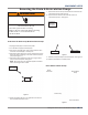
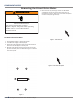
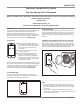

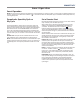

Table Of Contents
- Smart All-In-One Washer/Dryer
- Table of Contents
- Section 1: General Information
- Washer & Dryer Safety
- Introduction
- Features
- Options
- Accessories
- Control Panel & Features
- Control Panel - Tools
- Load & Go Bulk Dispenser
- Theory of Operation - Dry Cycle
- Product Specifications
- Wiring Diagram & Model/Serial Number Location
- Model & Serial Number Nomenclature
- All-In-One Washer/Dryer Maintenance
- Cleaning the Drain Pump Filter/Draining Residual Water
- How to Manually Open a Locked Door
- Section 2: Diagnostics & Troubleshooting
- Section 3: Component Testing
- Component Testing Safety
- Wiring Diagram
- TEST #1: Appliance Control Unit (ACU) Power Check
- TEST #2: Human-Machine Interface (HMI)
- TEST #3: Motor Circuit
- TEST #4: Door Lock System
- TEST #5: Inlet Valve
- TEST #6: Pressure Switch
- TEST #7: Drain/Recirculation Pump
- TEST #8: Wash Heating Element
- TEST #9: Wash Temperature Sensor
- TEST #10a: Dispenser Sensing
- TEST #10b: Dispenser Metering Pumps
- TEST #11: Supply Connections
- TEST #12a: Dry Heating Element
- TEST #12b: Dry Temperature Sensor
- TEST #13: Dry Fan Motor
- Section 4: Component Access
- Removing the Door Assembly
- Removing the Top Panel
- Replacing the Human-Machine Interface (HMI)
- Removing the Front Panel & Bulkhead
- Removing the Rear Access Panel
- Removing the Inlet Valve Assembly
- Removing the Pressure Switch
- Removing the Metering Pumps
- Removing the Detergent Dispenser
- Removing the Dryer Heating Channel Assembly
- Removing the Condenser Duct Assembly
- Removing the RFI Filter
- Removing the Door Lock Assembly
- Removing the Appliance Control Unit (ACU)
- Removing the Motor Control Unit (MCU)
- Removing the Heater & Thermistor
- Removing the Drain & Recirculation Pumps
- Removing the Direct Drive Motor
- Removing the Tub Assembly
- Section 5: Connectivity
- Product Specifications & Warranty Information Sources

4-20
n
Whirlpool Smart All-In-One Washer & Dryer
COMPONENT ACCESS
Removing the Direct Drive Motor
WARNING
Electrical Shock Hazard
Disconnect power before servicing.
Failure to do so can result in death or
electrical shock.
Replace all parts and panels before operating.
To Remove the Drive Motor
1. Unplug washer/dryer or disconnect power.
2. Turn o water supply to washer/dryer.
3. Disconnect cold inlet water hose and remove the drain
hose from the standpipe or laundry tub.
4. Remove six (6) Phillips screws securing the rear access
panel to the back panel as indicated in Figure 1. Remove
rear access panel.
Remove 6 Screws
Figure 1
5. Block the rotor by inserng a small 4 mm at-blade
screwdriver into the slot at the back of the rotor as
illustrated in Figure 2. Align slot in rotor with receptacle
on back of tub (see Figure 2 & 3).
Figure 2 - Lock Rotor Slot
Figure 3 - Lock Rotor Receptacle