
Service Manual

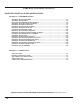
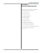

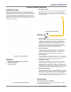
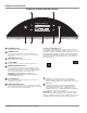

Table Of Contents
- Smart All-In-One Washer/Dryer
- Table of Contents
- Section 1: General Information
- Washer & Dryer Safety
- Introduction
- Features
- Options
- Accessories
- Control Panel & Features
- Control Panel - Tools
- Load & Go Bulk Dispenser
- Theory of Operation - Dry Cycle
- Product Specifications
- Wiring Diagram & Model/Serial Number Location
- Model & Serial Number Nomenclature
- All-In-One Washer/Dryer Maintenance
- Cleaning the Drain Pump Filter/Draining Residual Water
- How to Manually Open a Locked Door
- Section 2: Diagnostics & Troubleshooting
- Section 3: Component Testing
- Component Testing Safety
- Wiring Diagram
- TEST #1: Appliance Control Unit (ACU) Power Check
- TEST #2: Human-Machine Interface (HMI)
- TEST #3: Motor Circuit
- TEST #4: Door Lock System
- TEST #5: Inlet Valve
- TEST #6: Pressure Switch
- TEST #7: Drain/Recirculation Pump
- TEST #8: Wash Heating Element
- TEST #9: Wash Temperature Sensor
- TEST #10a: Dispenser Sensing
- TEST #10b: Dispenser Metering Pumps
- TEST #11: Supply Connections
- TEST #12a: Dry Heating Element
- TEST #12b: Dry Temperature Sensor
- TEST #13: Dry Fan Motor
- Section 4: Component Access
- Removing the Door Assembly
- Removing the Top Panel
- Replacing the Human-Machine Interface (HMI)
- Removing the Front Panel & Bulkhead
- Removing the Rear Access Panel
- Removing the Inlet Valve Assembly
- Removing the Pressure Switch
- Removing the Metering Pumps
- Removing the Detergent Dispenser
- Removing the Dryer Heating Channel Assembly
- Removing the Condenser Duct Assembly
- Removing the RFI Filter
- Removing the Door Lock Assembly
- Removing the Appliance Control Unit (ACU)
- Removing the Motor Control Unit (MCU)
- Removing the Heater & Thermistor
- Removing the Drain & Recirculation Pumps
- Removing the Direct Drive Motor
- Removing the Tub Assembly
- Section 5: Connectivity
- Product Specifications & Warranty Information Sources

1-6
n
Whirlpool Smart All-In-One Washer & Dryer
GENERAL INFORMATION
Theory of Operation
The illustraon below gives a brief descripon of the components involved specically on a Dry Cycle. Knowledge on the
system’s physical parts is needed in order to properly diagnose and troubleshoot the “all-in-one” washer/dryer.
1. Blower - Generates process air ow through the heater
channel, tub, and condenser duct.
2. Air Heater - Heats the air so it gets into the tub at high
temperature and reduced relave humidity.
3. Heater Channel - Conducts hot process air into the tub, so
it can remove humidity from the laundry.
4. Inlet Air NTC - Used as a feedback for the air heater
Control Soware.
5. Drain Pump - Pumps out condensed humidity and cooling
valve water that accumulates in the sump.
6. Sump NTC - Used as a feedback for the Auto-Dry Cycle
terminaon algorithms (apart from being used in heated
wash cycles).
7. Condenser Duct - Process air goes through condenser
duct to “get dry” - humidity is condensed and drained out
of the “all-in-one” washer/dryer.
8. Cooling Valve - Used to spray water into the condenser
duct, to cool down the process air and condense humidity.
Air Heater
Heater Channel
Blower
Inlet Air NTC
Drain Pump
Cooling Valve
Condenser Duct
Sump NTC
Dry Cycle - Illustraon
Figure 1 - Dry Cycle Theory of Operation
Dry Cycle - Theory of Operaon