
Specifications


4
The installation of the furnace, wiring, warm air ducts, venting,
etc., must conform to the requirements of the National Fire
Protection Association; the National Fuel Gas Code, ANSI
Z223.1/NFPA No. 54 (latest edition) and the National Electrical
Code, ANSI/NFPA No. 70 (latest edition) in the United States, and
any state laws, local ordinances (including plumbing or
wastewater codes), or local gas utility requirements.
Local authorities having jurisdiction should be consulted before
installation is made. Such applicable regulations or requirements
take precedence over the general instructions in this manual.
This furnace design is certified by CSA International as a
Category IV furnace in compliance with the latest edition of
American National Standard Z21.47/CSA Standard 2.3 for Gas-
Fired Central Furnaces, for operation with Natural gas or
propane. Consult the rating plate on the furnace for gas type
before installing.
Tools and Parts
Gather the required tools and parts before starting installation.
Read and follow the instructions provided with any tools listed
here.
Tools needed
Parts needed
Check local codes and with gas supplier. Check existing gas
supply, electrical supply, and venting, and read “Ductwork
Requirements,” “Electrical Requirements,” “Gas Supply
Requirements” and “Venting Requirements” before purchasing
parts.
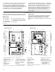
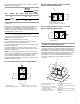
Component Identification
■ Pipe wrench
■ Screwdriver
■ Tape measure
■ Thread sealant
■ Level
■ Noncorrosive leak check solution
■ Test gauge with ¹⁄₈" NPT connection
(for measuring gas supply pressure)
■ Allen wrench
A. Combustion air intake connection
B. Transformer (40VA)
C. ECM variable speed circulator
blower
D. Flue pipe connection
E. Flue pipe
F. Pressure switches
G. Rubber elbow
H. Flue pipe connection (alternate)
I. Junction box
J. 2-speed induced draft blower
K. Electrical connection inlets
L. Coil front cover pressure tap
M. Coil front cover drain port
N. Drain line penetrations
O. Drain trap
P. Gas line entrance (alternate)
Q. 2-stage gas control valve
R. Gas manifold
S. Hot surface igniter
T. Rollout limit switch
U. Burners
V. Flame sensor
W. Primary limit switch
X. Gas line entrance
Y. Electrical connection inlets (alternate)
Z. Coil front cover
AA. Blower door interlock switch
AB. Auxiliary limit switch
AC. Inductor (on some models)
AD. 24-volt thermostat connections
AE. 2-stage integrated control
module (with fuse and
diagnostic LED)
AF. Combustion air inlet pipe
Q
VTUT RS
W
X
O
N
M
L
Z
AB
AE
AC
AD
AF
AB CD
F
G
H
J
L
M
N
P
E
Y
K
I
AA
Blower CompartmentBurner Compartment
Q
P
F
R
AST UTVD
E
F
W
X
H
G
J
L
M
N
AC
AD
AA
I
AEBC
AB
O
N
M
L
AA
Y
K
DEHUM
CUTFOR
*
*
*
*
**
*
*
*
Blower Compartment Burner Compartment
Counterflow/Horizontal Upflow/Horizontal