
Dimensions Guide


7
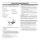
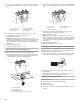
Backguard Assembly
1. Lower Backguard down while guiding the Backguard slots
down between the range top and the locking nuts.
2. Use the two assembly screws to attach the back corners of
the Backguard to the side panels.
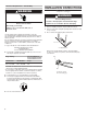
Install Anti-Tip Bracket
1. Remove the anti-tip bracket from inside the literature bag
assembly located in the oven.
Tools Required:
Phillips Screwdriver
Parts Supplied:
(2) Assembly Screws# lOA x
1/2 Phillips Pan Hd Screw
A
B
C
B
A. Backguard slot
B. Assembly screw
C. Locking nut
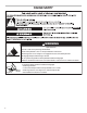
WARNING
Tip Over Hazard
A child or adult can tip the range and be killed.
Install anti-tip bracket to floor or wall per installation
instructions.
Slide range back so rear range foot is engaged in the
slot of the anti-tip bracket.
Re-engage anti-tip bracket if range is moved.
Do not operate range without anti-tip bracket installed
and engaged.
Failure to follow these instructions can result in death
or serious burns to children and adults.
2. Determine which mounting method to use: oor or wall.
If you have a stone or masonry oor, you can use the wall
mounting method. If you are installing the range in a mobile
home, you must secure the range to the oor.
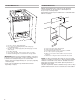
3. It is necessary to determine the nal location of the range
before you can locate the anti-tip bracket. If the range is
going to be located between cabinets, place the bracket so
that Edge A sits at against the rear wall. Edge B should just
touch the side of the cabinet sitting to the right side of the
range.
If there are no adjacent cabinets, align Edge B of the bracket
with the edge of the range side. After the bracket has been
placed mark the hole locations with a marker.
4. The anti-tip bracket can be attached to the oor or the wall.
For wall mount application use Location C. When using
location C, the screws must penetrate the wall sill plate
located within the wall. For oor mount application use
Location D or E. One screw on each side of the bracket is
sufcient.
5. To mount anchor bracket to concrete or ceramic oor, use
a drill with a 3/16" masonry bit to drill the two holes. Tap
plastic anchor into mounting holes in oor with hammer.
Line up holes in anti-tip bracket to holes in oor. Use the two
screws provided to fasten anti-tip bracket to oor.
6. Unscrew the rear leg levelers approximately 1/2" so that the
rear leg levelers will slide in under the anti-tip bracket. Slide
range into the nal position after completing the gas and
electrical connections to the range.
Edge A
Edge B
Anti-Tip Bracket
Location C
Location D
Location E
Location C