
Owner's Manual
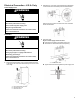
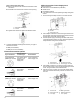
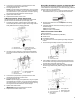
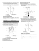
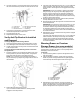
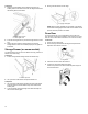
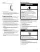
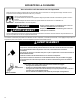
Table Of Contents
- RANGE SAFETY
- Range Safety
- RANGE MAINTENANCE AND CARE
- Steam Clean
- General Cleaning
- INSTALLATION INSTRUCTIONS
- REQUIREMENTS
- Tools and Parts
- Location Requirements
- Electrical Requirements - U.S.A. Only
- Electrical Requirements - Canada Only
- INSTALLATION
- Unpack Range
- Install Anti-Tip Bracket
- Adjust Leveling Legs
- Level Range
- Electrical Connection - U.S.A. Only
- Verify Anti-Tip Bracket Is Installed and Engaged
- Warming Drawer or Premium Storage Drawer (on some models)
- Storage Drawer (on some models)
- Oven Door
- Complete Installation
- Moving the Range
- SÉCURITÉ DE LA CUISINIÈRE
- Sécurité de la cuisinière
- ENTRETIEN ET RÉPARATION DE LA CUISINIÈRE
- Nettoyage à la vapeur
- Nettoyage Général
- INSTRUCTIONS D’INSTALLATION
- EXIGENCE
- Outillage et pièces
- Exigences d’emplacement
- Spécifications électriques – É.-U. seulement
- Spécifications électriques – Canada seulement
- INSTALLATION
- Déballage de la cuisinière
- Installation de la bride antibasculement
- Réglage des pieds de nivellement
- Réglage de l’aplomb de la cuisinière
- Raccordement électrique – É.-U. seulement
- Vérifier que la bride antibasculement est bien installée et engagée
- Tiroir-réchaud ou tiroir de remisage de qualité supérieure (sur certains modèles)
- Tiroir de remisage (sur certains modèles)
- Porte du four
- Terminer l’installation
- Déplacement de la cuisinière
- SEGURIDAD DE LA ESTUFA
- Seguridad de la estufa
- CUIDADO Y MANTENIMIENTO DE LA ESTUFA
- Limpieza con vapor
- Limpieza general
- INSTRUCCIONES DE INSTALACIÓN
- REQUISITOS
- Herramientas y piezas
- Requisitos de ubicación
- Requisitos eléctricos — EE. UU. únicamente
- Requisitos eléctricos – Solo en Canadá
- INSTALACIÓN
- Desempaque la estufa
- Instalación del soporte antivuelco
- Regule las patas niveladoras
- Nivelación de la estufa
- Conexión eléctrica — EE. UU. únicamente
- Verifique que el soporte antivuelco esté instalado y enganchado
- Cajón de calentamiento o cajón de almacenamiento Premium
- Cajón de almacenamiento (en algunos modelos)
- Puerta del horno
- Completar la instalación
- Cómo mover la estufa

13
6. Connect line 2 (red) and line 1 (black) wires to the outer
terminal block posts with 10-32 hex nuts.
7. Securely tighten hex nuts.
NOTE: For power supply cord replacement, use only a power
cord rated at 250 V minimum, 40 A or 50 A that is marked for
use with nominal 1
3
⁄
8
" (3.5 cm) diameter connection opening,
with ring terminals and marked for use with ranges.
8. Tighten strain relief screws.
9. Replace terminal block access cover.
3-Wire Connection: Power Supply Cord
Use this method only if local codes permit connecting chassis
ground conductor to neutral wire of power supply cord.
1. Feed the power supply cord through the strain relief in the
cord/conduit plate on bottom of range. Allow enough slack to
easily attach the wiring to the terminal block.
A. Terminal block
B. Ground-link screw
C. UL listed strain relief
D. Power supply cord wires -
large opening
2. Use 3/8" (9.5 mm) nut driver to connect the neutral (white)
wire to the center terminal block post with one of the 10-32
hex nuts.
A. 10-32 hex nut
B. Line 2 (red)
C. Ground-link screw
D. Neutral (white) wire
E. Line 1 (black)
3. Connect line 2 (red) and line 1 (black) wires to the outer
terminal block posts with 10-32 hex nuts.
4. Securely tighten hex nuts.
NOTE: For power supply cord replacement, only use a power
cord rated at 250 V minimum, 40 A or 50 A that is marked for
use with nominal 1
3
/
8
" (3.5 cm) diameter connection opening,
with ring terminals and marked for use with ranges.
5. Tighten strain relief screws.
IMPORTANT: Verify the tightness of the hex nuts.
6. Replace terminal block access cover.
Direct Wire Installation: Copper or Aluminum Wire
This range may be connected directly to the fuse disconnect or
circuit breaker box. Depending on your electrical supply, make the
required 3-wire or 4-wire connection.
1. Strip outer covering back 3" (7.6 cm) to expose wires. Strip
the insulation back 1" (2.5 cm) from the end of each wire.
2. Allow enough slack in the wire to easily attach the wiring
terminal block.
3. Complete electrical connection according to your type of
electrical supply.
4-wire (recommended)
3-wire (if 4-wire is not available)
4-Wire Connection: Direct Wire
Use this method for:
� New branch-circuit installations (1996 NEC)
� Mobile homes
� Recreational vehicles
� In an area where local codes prohibit grounding through the
neutral
1. Part of metal ground strap must be cut out and removed.
A. Metal ground strap
B. Discard
C. Ground-link screw
2. Use a Phillips screwdriver to remove the ground-link screw
from the back of the range. Save the ground-link screw and
the end of the ground link under the screw.
3. Pull the wires through the strain relief on bottom of range.
Allow enough slack to easily attach wiring to the terminal
block.
A. Terminal block
B. Ground-link screw
C. Cord/conduit plate
D. Bare (green)
ground wire
E. Line 2 (red) wire
F. Neutral (white) wire
G. Line 1 (black) wire