
Owner's Manual


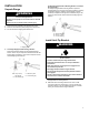
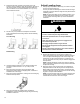
Table Of Contents
- RANGE SAFETY
- Range Safety
- RANGE MAINTENANCE AND CARE
- Self-Cleaning Cycle (on some models)
- General Cleaning
- INSTALLATION INSTRUCTIONS
- REQUIREMENTS
- Tools and Parts
- Location Requirements
- Electrical Requirements - U.S.A. Only
- Electrical Requirements - Canada Only
- INSTALLATION
- Unpack Range
- Install Anti-Tip Bracket
- Adjust Leveling Legs
- Level Range
- Electrical Connection - U.S.A. Only
- Verify Anti-Tip Bracket Is Installed and Engaged
- Warming Drawer or Premium Storage Drawer (on some models)
- Storage Drawer (on some models)
- Oven Door
- Complete Installation
- Moving the Range
- SÉCURITÉ DE LA CUISINIÈRE
- Sécurité de la cuisinière
- ENTRETIEN ET RÉPARATION DE LA CUISINIÈRE
- Programme d’autonettoyage (sur certains modèles)
- Nettoyage Général
- INSTRUCTIONS D’INSTALLATION
- EXIGENCE
- Outillage et pièces
- Exigences d’emplacement
- Spécifications électriques – É.-U. seulement
- Spécifications électriques – Canada seulement
- INSTALLATION
- Déballage de la cuisinière
- Installation de la bride antibasculement
- Réglage des pieds de nivellement
- Réglage de l’aplomb de la cuisinière
- Raccordement électrique – É.-U. seulement
- Vérifier que la bride antibasculement est bien installée et engagée
- Tiroir-réchaud ou tiroir de remisage de qualité supérieure (sur certains modèles)
- Tiroir de remisage (sur certains modèles)
- Porte du four
- Terminer l’installation
- Déplacement de la cuisinière
- SEGURIDAD DE LA ESTUFA
- Seguridad de la estufa
- CUIDADO Y MANTENIMIENTO DE LA ESTUFA
- Ciclo de autolimpieza
- Limpieza general
- INSTRUCCIONES DE INSTALACIÓN
- REQUISITOS
- Herramientas y piezas
- Requisitos de ubicación
- Requisitos eléctricos — EE. UU. únicamente
- Requisitos eléctricos – Solo en Canadá
- INSTALACIÓN
- Desempaque la estufa
- Instalación del soporte antivuelco
- Regule las patas niveladoras
- Nivelación de la estufa
- Conexión eléctrica — EE. UU. únicamente
- Verifique que el soporte antivuelco esté instalado y enganchado
- Cajón de calentamiento o cajón de almacenamiento Premium
- Cajón de almacenamiento (en algunos modelos)
- Puerta del horno
- Completar la instalación
- Cómo mover la estufa

10
3. Determine and mark centerline of the cutout space. The
mounting can be installed on either the left-side or right-side of
the cutout. Position mounting bracket against the wall in the
cutout so that the V-notch of the bracket is 12
9
/
16
" (31.9 cm)
from centerline as shown.
A. 12
9
/
16
" (31.9 cm)
B. Bracket V-notch
4. Drill two 1/8" (3 mm) holes that correspond to the bracket
holes of the determined mounting method. See the following
illustrations.
Floor Mounting
Rear Position Front Position Diagonal (2 options)
Wall Mounting
5. Using the Phillips screwdriver, mount anti-tip bracket to the
wall or floor with the two #12 x 1
5
/
8
" (41.3 mm) screws
provided.
6. Move range close enough to opening to allow for final
electrical connections. Remove shipping base, cardboard or
hardboard from under range.
7. Move range into its final location, making sure rear leveling leg
slides into anti-tip bracket.
8. Move range forward onto shipping base, cardboard or
hardboard to continue installing the range using the following
installation instructions.
Adjust Leveling Legs
1. If range height adjustment is necessary, use a wrench or pliers
to loosen the four leveling legs.
This may be done with the range on its back or with the range
supported on two legs after the range has been placed back to
a standing position.
NOTE: To place range back up into a standing position, put a
sheet of cardboard or hardboard in front of range. Using two
or more people, stand range back up onto the cardboard or
hardboard.
WARNING
Tip Over Hazard
A child or adult can tip the range and be killed.
Install anti-tip bracket to floor or wall per installation
instructions.
Slide range back so rear range foot is engaged in the
slot of the anti-tip bracket.
Re-engage anti-tip bracket if range is moved.
Do not operate range without anti-tip bracket installed
and engaged.
Failure to follow these instructions can result in death or
serious burns to children and adults.
2. Measure the distance from the top of the counter to the floor.
3. Measure the distance from the top of the cooktop to the
bottom of the leveling legs. This distance should be the same.
If it is not, adjust the leveling legs to the correct height. The
leveling legs can be loosened to add up to a maximum of 1"
(2.5 cm). A minimum of 3/16" (5 mm) is needed to engage the
anti-tip bracket.
NOTE: If height adjustment is made when range is standing,
tilt the range back to adjust the front legs, and then tilt forward
to adjust the rear legs.
4. When the range is at the correct height, check that there is
adequate clearance under the range for the anti-tip bracket.
Before sliding range into its final location, check that the anti-
tip bracket will slide under the range and onto the rear leveling
leg prior to anti-tip bracket installation.
NOTE: If a Trim Kit will be used, the top of the cooktop should
be higher than the counter. See the Installation Instructions
included with the Trim Kit for the correct height.