
Owner's Manual

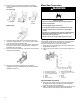
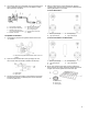

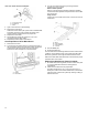

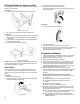

Table Of Contents
- RANGE SAFETY
- Range Safety
- RANGE MAINTENANCE AND CARE
- General Cleaning
- Self-Cleaning Cycle
- INSTALLATION INSTRUCTIONS
- REQUIREMENTS
- Tools and Parts
- Location Requirements
- Electrical Requirements
- Gas Supply Requirements
- INSTALLATION
- Unpack Range
- Install Anti-Tip Bracket
- Make Gas Connection
- Verify Anti-Tip Bracket Is Installed and Engaged
- Level Range
- Electronic Ignition System
- Warming Drawer or Premium Storage Drawer (on some models)
- Storage Drawer (on some models)
- Oven Door
- Complete Installation
- GAS CONVERSIONS
- Propane Gas Conversion
- Natural Gas Conversion
- Moving the Range
- SECURITE DE LA CUISINIERE
- Securite de la cuisiniere
- ENTRETIEN ET REPARATION DE LA CUISINIERE
- Nettoyage general
- Programme d'autonettoyage
- INSTRUCTIONS D'INSTALLATION
- EXIGENCE
- Outils et pieces
- Exigences d'emplacement
- Specifications electriques
- Specifications de l'alimentation en gaz
- INSTALLATION
- Deballage de la cuisiniere
- Installation de la bride antibasculement
- Raccordement au gaz
- Verifier que la bride antibasculement est bien installee et engagee
- Reglage de l'aplomb de la cuisiniere
- Systeme d'allumage electronique
- Tiroir-rechaud ou tiroir de remisage de qualite superieure (sur certains modeles)
- Tiroir de remisage (sur certains modeles)
- Porte du four
- Achever l'installation
- CONVERSIONS POUR CHANGEMENT DE GAZ
- Conversion pour l'alimentation au propane
- Conversion pour l'alimentation au gaz naturel
- Deplacement de la cuisiniere
- SEGURIDAD DE LA ESTUFA
- Seguridad de la estufa
- CUIDADO Y MANTENIMIENTO DE LA ESTUFA
- Limpieza general
- Ciclo de autolimpieza
- INSTRUCCIONES DE INSTALACION
- REQUISITOS
- Herramientas y piezas
- Requisitos de ubicacion
- Requisitos electricos
- Requisitos de suministro de gas
- INSTALACION
- Desembale la cocina
- Instalacion del soporte antivuelco
- Conexion del suministro de gas
- Verifique que el soporte anti-vuelco este instalado y enganchado
- Nivelacion de la cocina
- Sistema de encendido electronico
- Cajon de calentamiento o cajon de almacenamiento premium (en algunos modelos)
- Cajon de almacenamiento (en algunos modelos)
- Puerta del horno
- Completar la instalacion
- CONVERSIONES DE GAS
- Conversion a gas propano
- Conversion a gas natural
- Como mover la estufa

13
3. Use a 15/16" (23.8 mm) combination wrench and channel lock
pliers to attach the flexible connector to the adapters. Check
that connector is not kinked.
A. Gas pressure regulator
B. Use pipe-joint compound.
C. Adapter (must have 1/3"
[12.7 mm] male pipe thread)
D. Flexible connector
E. Manual gas shutoff valve
F. 1/2" (12.7 mm) or 3/4"
(19.1 mm) gas pipe
G. Use pipe-joint compound.
H. Adapter
Complete Connection
1. Check that the gas pressure regulator shutoff valve is in the
“on” position.
A. Gas pressure regulator shut-off valve shown in the “on”
position
2. Open the manual shutoff valve in the gas supply line. The
valve is open when the handle is parallel to the gas pipe.
A. Closed valve
B. Open valve
3. Test all connections by brushing on an approved noncorrosive
leak-detection solution. If bubbles appear, a leak is indicated.
Correct any leak found.
4. Remove cooktop burner caps and bases from package
containing parts. Place the burner bases as indicated by the
following illustration for your model:
For Model WFG515S0J :
A. Medium (Semi Rapid)
B. Large (Ultra Rapid)
D. Small (Auxiliary)
E. Large (Ultra Rapid)
For Models WFG525S0J and WFG535S0J:
A. Medium (Semi Rapid)
B. Large (Ultra Rapid)
C. Oval
D. Small (Auxiliary)
E. Large (Ultra Rapid)
5. Burner caps should be level when properly positioned. If
burner caps are not properly positioned, surface burners will
not light. Place burner grates over burners and caps.
A. Burner base
B. Burner cap
C. Burner grate