
Service Manual
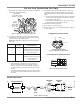
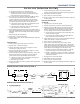
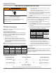
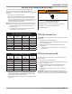
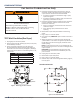
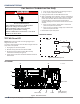
Table Of Contents
- Whirlpool & Maytag 27" Front-Load Gas & Electric Dryers
- Table of Contents
- Section 1: General Information
- Section 2: Diagnostics & Troubleshooting
- Section 3: Component Testing
- Testing - Safety Information
- Component Locations - Whirlpool
- Wiring Diagram - Whirlpool Electric
- Wiring Diagram - Whirlpool Gas
- Wiring Diagram - Maytag Electric
- Wiring Diagram - Maytag Gas
- Component Testing
- TEST #1: ACU Power Check
- TEST #2: Supply Connections
- TEST #3: Motor Circuit
- TEST #4: Heat System
- TEST #4a: Thermistors
- TEST #4b: Thermal Fuse
- TEST #4c: Thermal Cut-Off
- TEST #4d: Gas Valve (Gas Dryer)
- TEST #5: Moisture Sensor
- TEST #6: Buttons & Indicators
- TEST #7: Door Switch
- TEST #8: Drum LED
- TEST #9: Water Valve
- Section 4: Component Access
- Component Locations - Whirlpool
- Door Reversal - Round Shaped Doors
- Door Reversal - Square Shaped Doors
- Removing the Top Panel & Console/HMI
- Removing the Appliance Control Unit (ACU)
- Removing the Front Panel & Door Switch
- Removing the Drum Light & Moisture Sensor
- Removing the Belt, Drum, and Rollers
- Removing the Drive Motor
- Removing the Thermal Fuse & Outlet Thermistor
- Removing the Heater, High Limit Thermostat & Thermal Cutoff
- Removing the Ignitor, Flame Sensor, High-Limit Thermostat and Thermal Cutoff (Gas Models)
- Removing the Gas Burner Assembly Coils (Gas Models)
- Removing the Rear Panel
- Removing the Water Valve
- Section 5: Connectivity
- Product Specifications & Warranty Info

3-22
n
Whirlpool & Maytag Front-Load Dryers
COMPONENT TESTING
For Service Technician Use Only
DANGER
Electrical Shock Hazard
Only authorized technicians should perform
diagnostic voltage measurements.
After performing voltage measurements,
disconnect power before servicing.
Failure to follow these instructions can result in
death or electrical shock.
TEST #8: Drum LED
NOTE: Refer to the Drum LED circuit at right (Figure 2) to
diagnose the drum LED.
This test is performed if the drum LED does not light when the
dryer door is rst opened.
1. Unplug dryer or disconnect power.
2. Remove the top panel to access ACU and HMI.
3. Verify that the drum LED connector J6 is securely
connected to the ACU (see Figure 1).
4. Check harness and inline connecons between the drum
LED and ACU.
DRUM LED CIRCUIT
ACU
DRUM LED CIRCUIT
J6-1
R
BK
R
J6-2
BK
DRUM LED
¾ If the harness and connecons are good, go to step 5.
¾ If not, repair or replace as needed.
5. Unplug the drum LED connector J6 from the ACU.
6. With a mulmeter set to milliamps, connect mulmeter to
ACU connector J6, pins 1 and 3. Plug in dryer or reconnect
power. Open the door. Measure the current across ACU
connector J6, pins 1 and 3. If the drum LED driver is
working properly, there should be a measurement of 150-
370 mA.
¾ If the current is present, unplug dryer or disconnect
power and replace the drum LED.
¾ If the current is not present, unplug dryer or disconnect
power and replace the ACU.
7. Reassemble all parts and panels.
Figure 1 - Drum LED Connector
Figure 2 - Drum LED Strip Circuit
ACU BOARD
J13
J23
J2
J14
J6
J8
J9
Motor Relay
Heater-RED
L1-BLK
Heater Relay #1
(Gas & Electric)
• = Pin 1
K1
K2
K3