Electric Dryer Installation Instructions Table of Contents DRYER SAFETY 0. .ccccccccctceceeeeecceeesseeeeeeseeeeeeceneeseceeteseeeteeteenseeeats 2 INSTALLATION REQUIREMENTS. .......c:c::cscccssesetsececeessessneeeeeene 3 Tools atid Parts .....ccccccccceeeseseeeceseesenueneceseeesanaeseeeetenaeneeeesenuans 3 LOCATION REQUIREMENTS. .......2::cccccsssseeseeceseseneeeesesseessneeeenens 4 ELECTRICAL REQUIREMENTS. .......ccccsecscccesssetsececetseessneeeeeene 5 INSTALL LEVELING LEGS... .
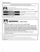
DRYER SAFETY Your safety and the safety of others are very important. We have provided many important safety messages in this manual and on your appliance. Always read and obey all safety messages. This is the safety alert symbol. This symbol alerts you to potential hazards that can kill or hurt you and others. All safety messages will follow the safety alert symbol and either the word “DANGER?” or “WARNING.
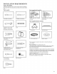
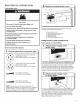
INSTALLATION REQUIREMENTS TOOLS AND PARTS Gather the required tools and parts before starting installation. Read and follow the instructions provided with any tools listed here.
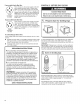
LOCATION REQUIREMENTS INSTALLATION CLEARANCES Location must be large enough to allow dryer door to open fully. AWARNING DRYER DIMENSIONS Models with riser |} — 22/4!" te —— (tn 39" (783 mm) (565 mm) CO 442" (1130 mm) Explosion Hazard Keep flammable materials and vapors, such as gasoline, away from dryer. 4" (102 mm) 5s! 63/4" (137 mm) a mmm) i Yo! {13 mm) Place dryer at least 18 inches (460 mm) above the floor for a garage installation.
Spacing for recessed area or closet installation ELECTRICAL REQUIREMENTS All dimensions show recommended spacing allowed, with tested spacing of 0” (0 mm) clearance on sides and rear. It is your responsibility: @ Additional spacing should be considered for ease of installation and servicing. @ Additional clearances might be required for wall, door, and floor moldings. @ Additional spacing should be considered on all sides of the dryer to reduce noise transfer.
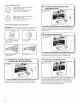
lf your outlet looks like this: Then choose a 4-wire power supply cord with ring or spade terminals and UL listed strain relief. The 4-wire power supply cord, at least 4 ft. (1.22 m) long, must have 4 10-gauge solid copper wires and match a 4-wire receptacle of NEMA Type 14-30 R. The ground wire (ground conductor) may be either green or bare. The —_ neutral conductor must be identified by a white cover.
ELECTRICAL CONNECTION (9. Remove terminal block cover Power Supply Cord Gh: 6 Fire Hazard Use a new UL listed 30 amp power supply cord. Use a UL listed strain relief. Disconnect power before making electrical connections. Connect neutral wire (white or center wire) to center terminal (silver). Before you start, disconnect power. Remove hold-down screw (D) and terminal block cover (A). A. B. C. D. E. F. Ground wire (green or bare wire) must be connected to green ground connector.
if your outlet looks like this: O | (NEMA Type 14-30R): ] 5] (¢ Power supply cord 4-wire receptacle Go to “4-Wire Power Supply Cord Connection” on this page. . Connect neutral ground wire and neutral wire ——= 2. Ge Power supply cord 3-wire receptacle (NEMA Type 10-30R): Go to “3-Wire Power Supply Cord Connection” on page 9. 4-wire Power Supply Cord Connection IMPORTANT: A 4-wire connection is required for mobile homes and where local codes do not permit the use of 3-wire connections.
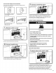
3-wire Power Supply Cord Connection Use where local codes permit connecting cabinet-ground conductor to neutral wire. 3-wire receptacle (NEMA type 10-30R) (3. Connect remaining wires 3-prong plug Connect remaining wires to outer terminal block screws. Tighten screws. Finally, reinsert tab of terminal block cover into slot of dryer rear panel. Secure cover with hold-down screw. Now, go to “Venting Requirements.” DIRECT WIRE CONNECTION Spade terminals with upturned ends Ring terminals Gh) f 1.
a . . (4 2. Prepare to connect neutral ground wire and neutral wire 2. Attach direct wire cable to strain relief Put direct wire cable through the strain relief. The strain relief should have a tight fit with the dryer cabinet and be in a horizontal position. Tighten strain relief screw against the direct wire cable. Remove center terminal block screw (B). Remove neutral ground wire (E) from external ground conductor screw (A).
a . . 5, Connect remaining wires a 3. Connect Place hooked ends of remaining direct wire cable wires under outer terminal block screws (hooks facing right). Squeeze hooked ends together and tighten screws. Finally, reinsert tab of terminal block cover into slot of dryer rear panel. Secure cover with hold-down screw. Now, go to “Venting Requirements.” 3-wire neutral wire Place hooked end of neutral wire (white or center) (C) of direct wire cable under center terminal block screw (B).
a 2. Connect neutral ground wire and neutral wire VENTING VENTING REQUIREMENTS Gh) é Fire Hazard Use a heavy metal vent. Do not use a plastic vent. Connect neutral ground wire (E) and neutral wire (white or center wire) (C) of power supply cord or cable under center terminal block screw (B). Tighten screw. (3 Do not use a metal foil vent. Failure to follow these instructions can result in death or fire.
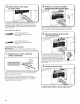
Exhaust hoods: @ Must be at least 12" (805 mm) from ground or any object that may obstruct exhaust (such as flowers, rocks, bushes, or snow). Recommended Styles: PLAN VENT SYSTEM Recommended exhaust installations Typical installations vent the dryer from the rear of the dryer. Other installations are possible. B Cc Sh Louvered Hood F Box Hood G Acceptable Style: B H Angled Hood A. Dryer E. Clamps B. Elbow C. Wall F. Rigid metal or flexible metal vent G.
lf you prefer, dryer may be converted to exhaust through the bottom. You must contact your local dealer to have dryer converted. Special provisions for mobile homes: Exhaust vent must be securely fastened to a noncombustible portion of mobile home and must not terminate beneath the mobile home. Terminate exhaust vent outside. A. Standard rear offset exhaust installation B. Bottom exhaust installation N Alternate installations for close clearances Venting systems come in many varieties.
CONNECT a Maytag Vent System Chart Number of Type Box/louvered hoods Angled 90° elbows of vent 0 Rigid metal 1 Rigid metal | 90 ft. (27.4 m) | 84 ft. (25.6 m) 2 Rigid metal | 80 ft. (24.4 m) | 74 ft. (22.6 m) 3 Rigid metal | 71 ft. (21.6 m) | 65 ft. (49.8m) 4 Rigid metal | 63 ft. (19.2 m) | 57 ft. (17.4 m) hoods The dryer must be connected to the cold water faucet using the new inlet hoses. Do not use old hoses. 4. |100 ft. (30.5 m) | 94 ft. (28.
( 4, Attach long hose to “Y” connector and tighten couplings (6. Turn on cold water faucet Gm ay ny One end of the long hose has a wire mesh strainer inside the coupling. Attach this end to the “Y” connector. Attach washer cold inlet hose to other side of “Y” connector. Screw on coupling by hand until it is seated on connector. Using pliers, tighten the couplings an additional two-thirds turn. NOTE: Do not overtighten. Damage to the coupling can result. (5.
CONNECT VENT LEVEL DRYER (a 1 » Gonnect vent to exhaust outlet (4 . Level Dryer Place level here Using a 4" (102 mm) clamp, connect vent to in dryer. If connecting to existing vent, make clean. Dryer vent must fit over dryer exhaust exhaust hood. Check that vent is secured to with a 4" (102 mm) clamp. ( 2. exhaust outlet sure vent is outlet and inside exhaust hood Move dryer to final location Check levelness of dryer from side to side. Repeat from front to back.
COMPLETE INSTALLATION CHECKLIST (-] Check that all parts are now installed. If there is an extra part, go back through steps to see what was skipped. (] Check that you have all of your tools. REVERSE DOOR SWING You can change your door swing from a right-side opening to a left-side opening, if desired. 1. Place a towel or soft cloth on top of dryer or work space to avoid damaging the surface. Remove the door assembly [-] Dispose of/recycle all packaging materials. 1. Open the dryer door.
Reverse the strike 1. Remove the door strike from the dryer door opening. §. Install screws in top hinge holes in the door. Do not tighten screws. Leave approximately 1/4" (6 mm) of screw exposed. = Z\ 2. Remove the cosmetic screw opposite the door strike. 4. Install the two hinges to the front panel of the dryer using 4 screws. Use the non-slotted side to attach the hinge to the front panel. A. Door strike B. Cosmetic screw 3.
W10562335A W10562339A-SP ®/™ © 2013. All rights reserved. 04/13 Printed in U.S.A.