
Installation guide


LOCATION
REQUIREMENTS
AWARNING
Explosion
Hazard
Keep
flammable
materials
and
vapors,
such
as
gasoline,
away
from
dryer.
Place
dryer
at
least
18
inches
(460
mm)
above
the
floor
for
a
garage
installation.
Failure
to
do
so
can
result
in
death,
explosion,
or
fire.
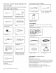
You
will
need:
@
A
location
allowing
for
proper
exhaust
installation.
See
“Venting
Requirements.”
@
A
separate
15
or
20
amp
circuit
for
a
gas
dryer
or
30
amp
circuit
for
an
electric
dryer.
@
If
using
power
supply
cord,
a
grounded
electrical
outlet
located
within
2
ft.
(610
mm)
of
either
side
of
dryer.
See
“Electrical
Requirements”.
@
Floor
must
support
dryer
weight
of
200
Ibs.
(90.7
kg).
Also
consider
weight
of
companion
appliance.
@
Cold
water
faucets
located
within
4
ft.
(4.2
m)
of
the
water
fill
valves,
and
water
pressure
of
20
-
120
psi
(138
-
827
kPa).
You
may
use
the
water
supply
for
your
washer
using
the
“Y”
connector
and
short
hose
(if
needed)
which
are
provided.
@
Level
floor
with
maximum
slope
of 1"
(25
mm)
under
entire
dryer.
If
slope
is
greater
than
1"
(25
mm),
install
Extended
Dryer
Feet
Kit,
Part
Number
279810.
If
not
level,
clothes
may
not
tumble
properly
and
automatic
sensor
cycles
may
not
operate
correctly.
@
For
garage
installation,
place
dryer
at
least
18"
(460
mm)
above
floor.
If
using
a
pedestal,
you
will
need
18"
(460
mm)
to
bottom
of
dryer.
@
The
dryer
must
not
be
installed
or
stored
in
an
area
where
it
will
be
exposed
to
water
and/or
weather.
IMPORTANT:
Do
not
operate,
install,
or
store
dryer
where
it
will
be
exposed
to
water,
weather,
or
at
temperatures
below
40°
F
(4°
C).
Lower
temperatures
may
cause
dryer
not
to
shut
off
at
end
of
automatic
sensor
cycles,
resulting
in
longer
drying
times.
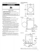
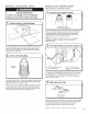
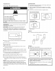
DRYER
DIMENSIONS
Front
view:
a7"
(686
mm)
L-
5
3816"
(968
mm)
=
3iqi*
(18
mm)
*
Approx.
measurement
Side
view:
507/s"
(1292
mm)
>
311/e"
;
(790
mm)
53/4"*
(146
mm)
32"
(89
mm)
\
a
en
enaenssnemaenesnanmmnmnssmmes
ommend
ona)
‘4
|
101/s"
|<
3/qh*
(18
mm)
(257
mm)
*
Approx.
measurement
Back
view:
—
pe!
6t/4"
(159
mm)
f
297/34"
(759
mm)
59)
Water
inlet
igi
*
(146
mm)
Vent
31/o"*
fo
(89
mm)
e—
Tp
y
Gas
(LL
r
‘TT
4
i
G1/_"*
We
156
18
|<
—1
43/e"
pp
(156
mm)
(18
mm)
(365
mm)
<0
25
9/4"
>|
(654
mm)
*
Approx.
measurement
NOTE:
Most
installations
require
a
minimum
of
5"
(127
mm)
clearance
behind
dryer
for
exhaust
vent
with
elbow.
See
“Venting
Requirements”.
5