
Troubleshooting guide


FOR SERVICE TECHNICIAN ONLY - DO NOT REMOVE OR DESTROY POURLETECHNICIEN SEULEMENT - NE PAS ENLEVERNIDÉTRUIRE
NECÈIP51EGAP10258369BW.ONTRAP
o
W10258369B
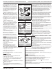
5. The console mounting bracketisfastened to
the console front panel with two latchesatboth
sidesofthe console assembly. Unlatch the
bracket gently withascrewdriver while pulling
the mounting bracket assembly out. See
figure 18.
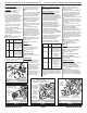
6. The console electronicsissplit into two
assemblies connectedbytwo cables. Each
assemblyisfastenedtothe decorative piece
by four plastic latches.Toremove these
assemblies, gently compress the plastic latches
w
hile pulling up on the assembly. For the cycle
selector assembly, the cycle selector knob must
firstberemovedbyfirmly pulling on it or gently
pryingitstraight upward. See figure 20.
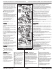
REMOVING THE BACKPANEL
1. Unplugdryerordisconnect power.
2. Remove the two rear screws from the top
panel, and slide the top paneltothe rear to
remove.
3. Remove the cover plate, disconnect the
power cord, and remove ground screw.
4. Remove the metal spring clip between the
back panel and the outlet outlet. See figure 21.
5. Remove the ten screwsonthe rear, and two
screwsonthe topofthe back panel. Pull the
back panel off the dryer.
ELECTRICDRYER:
In additiontothe above, remove the terminal
block from the back panel.
Remove the console panel
to access the console
electronics and housing
assembly.
Ôter le panneau de la
console pour accéder
à l’ensemble circuits
électroniques/carter.
Figure 18
EE
Gas Valve, Gas Dryer
Électrovanne à gaz, sécheuse à gaz
Locate eight
plastic latches.
es.
Localiser les huit
pattes de plastique.
Figure 20
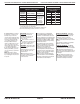
1M 2M 3M 5M 6M
Contacts
Function/Fonction
Start/Démarrage
Run/Fonctionnement
Centrifugal Switch (Motor)
Contacteur centrifuge (moteur)
Garniture
Remove the decorative trim. Retirer la garniture.
Figure 19
6. Les circuits électroniques de la console sont répartis sur deux
ensembles reliés par deux câbles. Chaque ensemble est fixé sur
la pièce décorative par quatre pattesdeplastique.Pour enlever
ces ensembles, appuyer doucement sur les pattesdeplastique
toutentirant sur l’ensemble.Pourlesélecteurdeprogramme, le
boutondusélecteur doit d’abord être retiré en le tirant fermement
ou en le levant doucement.Voir figure 20.
DÉPOSEDUPANNEAU ARRIÈRE
1. Débrancherlasécheuseoudéconnecterlasourcedecourant
électrique.
2. Ôter les deux vis arrièredupanneau supérieur, et faire glisser
le panneau supérieur vers l’arrière pour l’enlever.
3. Enleverlaplaquedecouverture; débrancherlecordon
d’alimentation; enleverlavisdeliaisonàlaterre.
4. Enlever l’agrafe métalliqueàressort entrelepanneau arrière
et la bouchededécharge.Voir figure 21.
5. Enlever les dix visàl’arrière,etles deux visausommet
du panneau arrière. Tirer pour séparerlepanneau arrière
de la sécheuse.
SÉCHEUSE ÉLECTRIQUE:
En plus des opérations ci-dessus, séparerleblocdeconnexion
du panneau arrière.
Remove 12 screws. Ôter 12 vis.
Figure 21
Black-White
Noir-blanc
Lt. Blue
Bleu clair
Green-Yellow
Vert-jaune
Red
Rouge
Red
Rouge
Pluggable Drive Motor Switch
Contacteur du moteur d’entraînement enfichable
SOFTWARE COPYRIGHTED. MANUFACTURED UNDER
ONE OR MORE OF THE FOLLOWING CANADIAN PATENTS:
LOGICIEL ASSUJETTI AUX DROITS D’AUTEUR. FABRIQUÉ SOUS
UN OU PLUSIEURS DES BREVETS CANADIENS SUIVANTS :
1273387 1315539 2016304
= Contacts closed/Contacts fermés
Black Noir
Blue Bleu
White Blanc
White Blanc
Blue Bleu