
Troubleshooting guide


FOR SERVICE TECHNICIAN ONLY - DO NOT REMOVE OR DESTROY POURLETECHNICIEN SEULEMENT - NE PAS ENLEVERNIDÉTRUIRE
NECÈIP8EGAP10258369BW.ONTRAP
o
W10258369B
SÉCHEUSE ÉLECTRIQUE SEULEMENT:
Contrôlerlefusible thermique.Voir
TESTn
o
4b, page 11.
TOUTES LES SÉCHEUSES:
Poursuivre
avec l’étape 4 ci-dessous et tester les
autres composants du circuit du moteur.
4. Contrôlerlecontacteurdutensionneur
de courroie et le moteur d’entraînement. Ôter
le panneau arrière pour accéderaumoteur
d’entraînement et au contacteur du
tensionneurdecourroie.Voir Dépose
du panneau arrière, page 15. Séparer
lentementlacourroiedutambourdela
pouliedetensionnement chargée par
ressort; laisserlapouliedetensionnement
descendre doucement.Voirlafigure 7.
5. Débrancherleconnecteur blanc
du contacteurdumoteur. Voir figure 8.
6. Débrancherleconnecteurduconducteur
de cuivre nu de la broche5ducommutateur
noirdumoteur. Voir figure 9.
7. Consulterlafigure9.Mesurer les valeurs
de résistance des bobinagesdumoteur
(bobinage principaletbobinage de
démarrage).Voirletableau suivant.
NOTE:On doit contrôler les bobinages
principal et de démarrage surlemoteur.
Bobinage
Rés.
Points
de mesure
Principal
3,3–3,6
Conducteur bleu clair à
l’arrière sur broche 4,
et conducteur de
cuivre nu déconnecté
de la broche 5 du
contacteur noir du
moteur
d’entraînement.
Démarrage
2,7–3,0
Conducteur bleu clair à
l’arrière sur broche 4,
et conducteur de
cuivre nu sur la
broche 3 du
contacteur noir
du moteur
d’entraînement.
Si la résistancedubobinagedumoteur
est correcte,ildoityavoiruncircuit ouvert
entrelemoteuretlemoduledecommande
électronique de la machine. Déterminersile
contacteurdutensionneurdecourroie est
défaillant.
ELECTRICDRYER ONLY:
Check the
thermal fuse. See TEST #4b, page 11.
ALLDRYERS: Continue with step 4
below to test the remaining
components in the motor circuit.
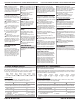
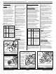
4. Check the belt switch and drive
motor. Access the belt switch and drive
motorbyremoving the back panel. See
Removing the BackPanel, page 15.
Slowly remove the drum belt from the
spring-loaded belt switch pulley, gently
letting the belt switch pulley down.
See figure 7.
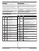
5. Remove the white connector from
the drive motor switch. See figure 8.
6. Remove the bare copper wire
terminal from pin 5 of black drive motor
switch. See figure 9.
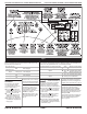
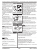
7. Using figure9,check for the
resistance valuesofthe motor’s Main
and Startwinding coilsasshowninthe
following table.
NOTE: Main and Start winding coils
must be checked at the motor.
Winding
R
es.
C
ontact Points of
Measurement
Main
3.3–3.6
Lt. blue wireinback
at pin 4 and bare
copper wire terminal
removed from pin5
of black drive motor
switch
Start
2.7–3.0
Lt. blue wireinback
at pin 4 and bare
copper wire terminal
on pin 3 of black
drive motor switch
If the resistanceatthe motor is
correct, there is an open circuit between
the motor and machine control
1
5
3
4
6
2
Start Winding:
Lt.
and Bare
Copper Wire
Blue Wire in
Back
Circuit de
démarrage :
conducteur
bleu clair à
l’arrière, et
conducteur de
cuivre nu
Bobinage principal : conducteur bleu clair
à l’arrière, et conducteur de cuivre nu
Main Winding: Lt.
and Bare Copper Wire
Blue Wire in Back
Main and start winding
measure points.
Points de mesure pour les
bobinages du moteur.
Figure 9
Drum Belt
Courroie du
tambour
Belt Switch Pulley
Poulie de tensionnement
Slowly remove
drum belt.
Enlever lentement la
courroie du tambour.
Figure 7
1
5
3
4
6
2
Belt Switch
Contacteur du
tensionneur de courroie
Belt Switch Pulley
Poulie de tensionnement
Conducteurs
bleu clair
Lt. Blue
Wires
Checking the belt
switch.
Contrôler le contacteur du
tensionneur de courroie.
Figure 10
1
5
3
46
2
Connecteur
blanc
Drive Motor Switch
Contacteur du moteur
White
Connector
Remove white
connector.
Débrancher le
connecteur blanc.
Figure 8
electronics. Check for failed belt switch.
If the Start winding resistance is
much greater than3Ω, replace the
motor.
8. Check the belt switchbymeasuring
resistance between the two light blue
wires,asshowninfigure 10, while
pushingupthe belt switch pulley.
If the resistance reading goes from
infinitytoafew ohmsaspulleyarm
closes the switch, belt switchisOK.
If not, replace the belt switch.
If belt switch is OK and thereisstill
an open circuit, check and repair the
wiring harness.
9. Door Switch problems can be
uncoveredbyfollowing procedure
under DIAGNOSTIC: Door Switch,
page2;however, if this was not done,
the following canbedone without
applying powertothedryer. Connect an
ohmmeter across P8-3 (neutral, white
wire) and P8-4 (door, tan wire).
With the door properly closed, the
ohmmeter should indicateaclosed
circuit (0–2 Ω).
If not, replace the door switch
assembly.
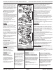
TEST#4 Heater
This testisperformed when either
of the following situations occur:
Dryer does not heat
Heat will not shut off
Dryer does not heat:
Locate the components using figure 11,
page 9.
ELECTRICDRYER:
1. Unplugdryerordisconnect power.
Si la résistance de la bobine de
démarrage est bien supérieureà3
,
remplacerlemoteur.
8. Contrôlerlecontacteurdutensionneur
de courroie:mesurerlarésistance entre
les deux conducteurs bleu clair (voir la
figure 10) toutenpoussant verslehaut
la pouliedetensionnement.
Si la résistance mesurée passedel’infini
à quelques ohms lors de la fermeture du
contacteur, le contacteur de la courroie est
en bon état. Sinon, remplacerlecontacteur
de la courroie.
Si le contacteur de la courroie esten
bon étatets’il y a toujoursuncircuit ouvert,
contrôleretréparerlecâblage.
9. Le processusdeDIAGNOSTIC:
contacteur de la porte, page2,permet
d’identifier des problèmesducontacteur de
la porte; cependant,sicela n’a pas été fait,
on peut exécuter les opérations suivantes
sans mettrelasécheuse sous tension.
Brancherunohmmètre entre les points P8-3
(neutre, conducteur blanc)etP8-4 (porte,
conducteur tan).
Lorsquelaporte est correctement
fermée,ondoit mesurer une résistance
de 0 à 2
(circuit fermé).
Sinon, remplacerlecontacteur
de la porte.
TESTN
o
4 Systèmedechauffage
On exécutecetest lorsque l’une des
situations suivantessemanifeste:
Absence de chauffage
Impossibilité d’arrêt du chauffage
Absence de chauffage :
À l’aide de la figure 11, page9,identifier
les composants.
SÉCHEUSE ÉLECTRIQUE:
1. Débrancherlasécheuseoudéconnecter
la sourcedecourant électrique.
2. Enleverlepanneaudeplinthe pour
accéder aux composantsdusystème
de chauffage.Voir Déposedupanneau
de plinthe, page 13.
3. Utiliserleschémadecâblageetun
ohmmètre; mesurerlarésistance entre la
broche rougesurlecoupe-circuit thermique
et la broche rougesurl’élément chauffant.
2. Remove the toe panel
to access the thermal
components. SeeRemoving
theToePanel, page 13.
3. Usinganohmmeter
and referringtothe wiring
diagram, measure the
resistance from the red
wire terminalatthe thermal
cut-offtothe red wire
terminalatthe heater.