
Troubleshooting guide


FOR SERVICE TECHNICIAN ONLY - DO NOT REMOVE OR DESTROY POURLETECHNICIEN SEULEMENT - NE PAS ENLEVERNIDÉTRUIRE
NECÈIP9EGAP10258369BW.ONTRAP
o
W10258369B
If the resistanceisabout 10 Ω, go to step 5.
If an open circuitisdetected, go to step 4.
4. Visually check the wire connectionstothe
thermal cut-off, high limit thermostat, and heater.
If connections look good, check for continuity
across eachofthese components.
Replace the heater if it is electrically open.
Replace both the thermal cut-off and
high limit thermostat if either the thermal
cut-offorthe high limit thermostatis
electrically open.
5. If no open circuitisdetected, remove the P14
connector, then measure the resistance between
P14-3 (red wire) and P14-6 (red wire)atthe
connector. See figure 17, page14for connector
location; and Accessing&Removing the
Electronic Assemblies, page 14.
If 5–15kΩ are measured, replace the
machine control electronics.
If the resistanceisless than1kΩ, replace
the outlet thermistor.
GASDRYER:
1. Unplugdryerordisconnect power.
2. Remove the toe paneltoaccess the thermal
components. SeeRemoving theToePanel,
page 13.
3. Perform TEST #4b, page 11.Ifthe thermal
fuseisOK, go to step 4.
4. Perform TEST #4c, page 11.Ifthe thermal
cut-offisOK, go to step 5.
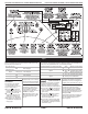
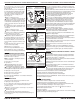
5. Locate the high limit thermostat. See figure 11.
Measure the continuity through it by connecting
the meter probesonthe red wire and black wire
terminals.
If there is an open circuit, replace the high
limit thermostat and thermal cut-off.
Otherwise, go to step 6.
6. Perform TEST #4d, page 11.IfthisisOK,
replace the machine control electronics.
Heat will not shut off:
1. Unplugdryerordisconnect power.
2. Access the machine control electronics. See
figure 17, page14for connector location; and
Accessing&Removing the Electronic
Assemblies, page 14.
ALL DRYERS:
Remove the P14 connector, then
measure the resistance betweenP14-3 (red wire)
and P14-6 (red wire) at the connector.
Si la résistance est d’environ 10 , passeràl’étape 5.
S’il y a un circuit ouvert, passeràl’étape 4.
4. Inspecter visuellement les connexions des conducteurs sur le
coupe-circuit thermique,lethermostatdetempérature maximum
et l’élément chauffant.Siles connexions sontenbon état, contrôler
la continuité à travers chacundeces composants.
Remplacer l’élément chauffant s’il est affecté paruncircuit
ouvert.
Remplacerlecoupe-circuit thermiqueetle thermostat
de température maximumsile coupe-circuit thermiqueou
le thermostatdetempérature maximum manifesteun
circuit ouvert.
5. S’il n’yaaucun circuit ouvert, débrancherleconnecteur P14 et
mesurerlarésistance entre P14-3 (conducteur rouge)etP14-6
(conducteur rouge)auconnecteur. Pourlapositionduconnecteur,
voirlafigure 17, page 14;etModules électroniques–Accès et
dépose, page 14.
Si on mesure une résistancede 5 à 15 k , remplacerlemodule
de commande électronique de la machine.
Si la résistance est inférieureà1k , remplacerlathermistance
du circuitdedécharge.
SÉCHEUSEÀGAZ:
1. Débrancherlasécheuseoudéconnecterlasourcedecourant
électrique.
2. Enleverlepanneaudeplinthe pour accéder aux composantsdu
système de chauffage. Voir Déposedupanneaudeplinthe, page 13.
3. ExécuterleTESTn
o
4b, page 11. Si le fusible thermique est en
bon état, passeràl’étape 4.
4. ExécuterleTESTn
o
4c, page 11. Si le coupe-circuit thermique est
en bon état, passeràl’étape 5.
5. Identifierlethermostatdetempérature maximum; voir la
figure 11. Contrôlerlacontinuité à traverslethermostat:connecter
l’instrument sur les broches rougeetnoir.
S’il y a un circuit ouvert, remplacerlethermostatdetempérature
maximum et le coupe-circuit thermique.
Sinon, passeràl’étape 6.
6. ExécuterleTESTn
o
4d, page 11.Sil’électrovanne estenbon état,
remplacerlemoduledecommande électronique de la machine.
Impossibilité d’arrêt du chauffage :
1. Débrancherlasécheuseoudéconnecterlasourcedecourant
électrique.
2. Accéderaumoduledecommande électronique de la machine.
Pourlapositionduconnecteur, voirlafigure 17, page 14; et
Modules électroniques–Accèsetdépose, page 14.
TOUTES LES SÉCHEUSES :
Débrancher le connecteur P14
et mesurer la résistance entre P14-3 (conducteur rouge) et P14-6
(conducteur rouge) au connecteur.
If 5–15kΩ aremeasured, replace the
machine control electronics.
If the resistanceisgreater than
20 kΩ, replace the outlet thermistor.
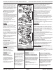
TEST #4a Thermistors
Outlet Thermistor
The machine control electronics
monitors the exhaust temperature
using the outlet thermistor, and
cycles the heater relayonand off
to maintain the desired temperature.
Begin withanemptydryer anda
clean lint screen.
1. Plug in dryerorreconnect power.
2. Start the TimedDrycycle.
Si on mesure une résistancede 5 à 15 k ,
de commande électronique de la machine.
Si la résistance estsupérieureà20k ,
du circuit de décharge.
TESTN
o
4a Thermistances
Thermistance du circuit de décharge
Le moduledecommande électroniquede
la machine assureunsuivi de la température
dans le circuitdedécharge,aumoyen d’une
thermistance du circuit de décharge; l’alimentation
intermittentedurelaisducircuitdechauffage
permetdemaintenirlatempérature désirée.
Travailler sur une sécheuse vide, avec tamis
à charpie propre.
1. Brancherlasécheuseoureconnecter
la sourcedecourant électrique.
Thermal components,
viewed from front.
Composants du système de
chauffage - vue de face.
Figure 11
2. Lancerleprogramme TimedDry(séchage
minuté).
3. Si après60secondesonobtient le
clignotementducode
ou sur
l’afficheur alors quelamachine s’arrête,ilya
un court-circuitoucircuit ouvert affectant la
thermistance ou le câblage.
Débrancherlasécheuseoudéconnecter
la sourcedecourant électrique.
Contrôler les branchements sur les broches
du moduledecommande électroniquedela
machine et la thermistance.Voirlapage14-
Modules électroniques–Accèsetdépose,
et la figure11pour l’emplacementdela
thermistance.
Si la qualité des connexions est bonne,
mesurerlarésistance de la thermistance
de sortie (étape5,page 10).
3.
If after60seconds,
F
:
22 or
F
:
23
flashesinthe display and thedryer
shuts off, the thermistororwire
harnessiseither openorshorted.
Unplugdryerordisconnect
power.
Check wire connectionsatthe
machine control electronics and
thermistor. See Accessing&
Removing the Electronic Assemblies
on page 14, and for thermistor
location see figure 11.
If wire connections are OK,
check the outlet thermistor
resistance per step5,page 10.
F
:
22
F
:
23
remplacer le module
remplacer la thermistance