
Specifications


10
Direct Vent Installation Upflow Models
■ Refer to the appropriate vent table for proper pipe size, vent
length and the number of elbows allowed, and air intake
length and the number of elbows allowed.
■ Refer to the “Materials” section for the proper venting
material.
■ Do not install the inlet air restrictor plate in any direct vent
installation. The inlet air restrictor plate (see “Inlet Air
Restrictor Plate” section) supplied with this furnace is to be
used only in non-direct vent applications.
■ The flue pipe screen, designed to keep objects out of the flue
pipe (see “Flue Pipe Screen” section), should be installed at
the termination of the flue pipe.
NOTE: Do not place an additional flue pipe screen in the
intake termination because the air intake may freeze shut.
■ For proper operation, the vent and air intake pipe must be
installed in the same pressure zone. Therefore, in horizontal
venting applications they must be on the same side of the
house within the parameters as shown.
NOTE: The 18 in. dimension shown below is the minimum
recommended height for extremely cold areas. In these
areas, moisture in the flue gases may condense and freeze on
the air intake if this height is reduced. In milder climates, this
may be reduced to a minimum of 6 in. Height may be
increased as needed provided total length of pipe to furnace
is not exceeded.
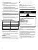
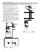
Direct Vent-Upflow (Horizontal Venting)
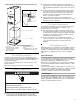
Direct Vent - Upflow (Vertical Venting)
1. Air intake pipe
2. Condensate collar
3. Optional piece
4. Flue pipe screen (inside flue pipe)
5. Flue pipe
6. Air intake pipe
7. Wall
(CLOSED)
DRAIN HOLE
THRU.
59.69/56.64
18"
Run Ptich = 1/4"
Per Foot Min.
Height to Provide
12" Clearance to
Max. Snow Level.
6"
1
2
3
5
4
6
7
3" Min. - 48" Max.
Overhead View
3
7
5
6
1. Flue pipe
2. Condensate collar
3. Flue pipe screen (inside flue pipe)
4. Storm collars
5. Flashing
6. Air intake pipe
6.5" Min. - 24" Max.
10 Ft.
Min.
2 Ft.
Min.
Run Pitch = 1/4"
Per Foot Min.
1
2
4
3
5
6