
Specifications


9
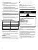
Vent Table - 112,000 - 125,000 BTU/HR Models
In the event that the pipe length is in between the lengths listed in
the Vent Table, use the next larger length listed. For example, if a
length of pipe needed to install the furnace is 27 ft, use the
diameter values for the 30 ft row in the tables.
For direct vent installations, if the vent and air intake pipe are not
equal in length and number of elbows, then determine the
minimum pipe diameter for both the vent and air intake. If the
results indicate different diameters, use the larger of the two for
both the vent and air intake.
NOTE: Under no circumstances should the vent and air intake
pipe size be different in diameter. See “Install Vent System” for
the unit model and type of installation.
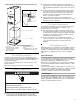
Determine Vent Pipe Direction
The vent system of the furnace must be self-supporting and must not apply any weight load to the combustion blower.
Combustion Air Sources
There are 2 sources for combustion air:
1. From outside the building (Direct Vent)
2. From inside the building (Non-Direct Vent)
Please read the information provided here about Vertical and
Horizontal Venting, then find and follow the instructions for your
venting configuration.
Vertical Venting
A vertical vent should extend through the roof a minimum of 2 ft
and not be obstructed a minimum of 10 ft in any direction.
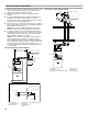
Horizontal Venting
The vent terminal location shall comply with Section 7.8 of the
National Fuel Gas Code (ANSI Z223.1) or local requirement,
whichever takes precedence. For informational purposes, the
applicable sections of Section 7.8 are reprinted here:
The venting system shall terminate at least 3 feet (0.9 m)
above any forced air inlet located within 10 feet (3.1 m).This
provision shall not apply to the combustion air inlet of a direct
vent appliance or to the separation of the circulating air inlet
and vent discharge of a listed outdoor appliance.
For non-direct vent installation, the vent system shall
terminate at least 4 feet (1.2 m) below, 4 feet (1.2 m)
horizontally from, or 12 inches (30 cm) above any door,
window, or gravity inlet into any building.The bottom of the
vent terminal shall be located at least 12 inches (30 cm)
above grade or maximum expected snow depth.
For direct vent installation of models with an input rating of
50,000 BTUH or less, the vent system shall terminate at least
9 inches (23 cm) from any opening through which flue gases
could enter a building. For direct vent installation of models
with an input greater than 50,000 BTUH, the vent system
shall terminate at least 12 inches (30 cm) from any opening
through which flue gases could enter a building.
Regardless of input, the vent terminal and air intake shall
terminate at least 12 inches (30 cm) above grade or maximum
expected snow depth.
The vent system, regardless of installation type, shall
terminate a minimum horizontal clearance of 4 ft from electric
meters, gas meters, regulators, and relief equipment.
Vent Pipe
Length (ft)
Minimum Pipe Diameter (in.)
5 2.5 2.5 2.5 2.5 2.5 2.5 2.5 2.5 2.5 2.5
10 2.5 2.5 2.5 2.5 2.5 2.5 2.5 2.5 2.5 3
20 2.5 2.5 2.5 2.5 2.5 2.5 2.5 3 3 NR
30 2.5 2.5 2.5 2.5 2.5 3 3 NR NR NR
40 2.5 2.5 2.5 2.5 3 NR NR NR NR NR
50 2.5 3 3 NRNRNRNRNRNRNR
60 3 3 NR NR NR NR NR NR NR NR
Number of 90°
Elbows
0 123456789
NR = Not Recommended