How to install, operate and maintain your Reverse Osmosis Drinking Water System Do not return unit to store If you have any questions or concerns when installing, operating or maintaining your reverse osmosis system, call our toll free number: 1-866-986-3223 Monday- Friday, 8 AM - 7 PM EST or visit www.whirlpoolwatertreatment.com When you call, please be prepared to provide the model, date code and serial number of your product, found on the rating decal, located inside the cover.
DO NOT RETURN TO STORE Need Help? Call toll free at: 1-866-986-3223 8:00 a.m. - 7:00 p.m.
Things to remember! = = = = = It will take time before water is available at the faucet. It may take 1-4 hours before maximum possible flow is available from the faucet. Water pressure from the Reverse Osmosis faucet will be less than your standard faucet due to the high level of filtration performed by the system. The faucet can be mounted in an existing hole in the sink (sprayer, soap dispenser etc.) or a new hole can be drilled.
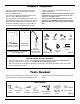
TABLE OF CONTENTS Page Specifications & Dimensions . . . . . . . . . . . . . . . . . . . . . . . . . . . . . . . . . . . . . . . . . . . . . . . . . . . . . . . . . . . . . . . . . . . 5 Inspect Shipment . . . . . . . . . . . . . . . . . . . . . . . . . . . . . . . . . . . . . . . . . . . . . . . . . . . . . . . . . . . . . . . . . . . . . . . . . . . . 6 Tools Needed . . . . . . . . . . . . . . . . . . . . . . . . . . . . . . . . . . . . . . . . . . . . . . . . . . . . . . . . . . . . . . . . . . . . . .
Specifications & Dimensions Supply water pressure limits . . . . . . . . . . . . . . . . . . . . . . . . . . . . . . . . . . . . . . . . . . . . . . 40-100 psi (280-689 kPa) Supply water temperature limits . . . . . . . . . . . . . . . . . . . . . . . . . . . . . . . . . . . . . . . . . . . . . 40-100 °F (4.5-37.7°C) Maximum total dissolved solids (TDS) . . . . . . . . . . . . . . . . . . . . . . . . . . . . . . . . . . . . . . . . . . . . . . . . . . 2000 ppm Maximum water hardness @ 6.9 pH . . . . . . .
Inspect Shipment Your Reverse Osmosis Drinking Water System is shipped complete in one carton. Remove all items from your shipping carton. Keep the small parts in the parts bag until you are ready to install them. Note any damage to the shipping carton. Refer to the exploded view and parts list in the back of the manual for the part names and numbers of missing or damaged items. If problems exist, refer to the website or the toll free number listed throughout this manual.
Plan Your Installation Read through the entire manual before beginning your installation. Follow all steps exactly. Reading this manual will also help you get all the benefits from your system. NOTE: For best system performance, the feed water to the system should be softened or have hardness less than 10 grains per gallon, with no iron. Your Reverse Osmosis Drinking Water System can be installed under a sink or in a remote location. Typical remote sites are a laundry room or utility room.
Overview and Site Preparation OVERVIEW PREPARE SITE FOR INSTALLATION There are seven steps to installing your Drinking Water system. They are as follows: 2. Temporarily place tank and filter assembly into planned location. Check position of items and space required for proper installation. Ensure tubes may be routed without kinking. Read through the entire manual before beginning your installation. 1. Before starting, close the hot and cold water shutoff valves (See Figure 6).
Step A - Install Supply Water Fitting CHOOSE TYPE OF WATER FITTING TO INSTALL Check and comply with local plumbing codes as you plan, then install a cold feed (supply) water fitting. Refer to the Specifications page for supply water requirements. The fitting must provide a leak-tight connection to the RO 1/4" tubing. A typical connection using the included water supply fitting is shown in Figure 6.. An optional connection using standard plumbing fittings (not included) is shown in Figure 6B.
Step B - Install RO Drain Under Sink INTRODUCTION Single trap A suitable drain point is needed for the drain water from the Reverse Osmosis Filter. You have two options to choose from: • Install the Drain Adapter included with your unit See Fig 7, Fig. 8, and Fig. 9. This is used in under the sink installations. The drain adapter kit is installed onto your sink drain pipe above the P-trap. See Fig. 7.
Step B - Install RO Drain in Remote Location Outside Faucet (Hard Water) Soft, Cold Water Hard W ater Lin e Soft, Hot Water Outside Faucet (Hard Water) Soft water to Reverse Osmosis System Shutoff Valve Remote Installation Location RED Tubing to Drain 1/4'' RED Tubing Sump 1-1/2” Air Gap 1-1/2” Air Gap Stand pipe 1-1/2” Air Gap Reverse Osmosis System YELLOW Tubing to Storage Tank Water Meter Water Softener GREEN Tubing to Reverse Osmosis System Reverse Osmosis Drain - RED Tubing to Drain
Step C - Install RO Filter Assembly INSTALL REVERSE OSMOSIS FILTER ASSEMBLY Hanger Washer (2) The Reverse Osmosis Filter Assembly is mounted on hanger washers. Screw (2) 9'' See Fig 12. The hanger washers allow you to lift the filter assembly from the washers without any hardware removal. When planning your installation, you need to leave room for changing filters. Complete the following steps to install your Reverse Osmosis Filter Assembly: 1. Remove the cover. 15-1/2'' minimum up from floor.
Step E - Install RO Faucet SELECT LOCATION OF REVERSE OSMOSIS FAUCET MOUNTING HOLE You will need to select the location of the Reverse Osmosis Faucet. You have three options to choose from: • Use the existing sink top hole for the spray hose or soap dispenser (Must be 1-3/8” in diameter) • Drill a new hole in the sink • Drill a new hole in the countertop next to the sink 1. Determine where you are going to install your Reverse Osmosis Faucet. 2.
Step E - Install RO Faucet (cont.) INSTALL REVERSE OSMOSIS FAUCET 1. Locate and organize your RO faucet install parts. Refer to Fig. 15. 2. Mount faucet base to sink hole until the faucet base is flat against the sink surface. The rubber gasket should be between the sink surface and the faucet base. 3. Tighten the toggle bolts until the base is firmly mounted to the sink surface. Do not overtighten. 4. Locate the faucet body. (The black and blue tubes are already connected to the faucet.
Step F - Connect Tubes HOW TO CUT AND CONNECT THE TUBES Foam Plug Your Reverse Osmosis system includes push-in fittings for quick tubing connection. Review the following instructions before connecting the tubes in the next step. Failure to follow these instructions may lead to future leaks. Push-in Fitting Remove and Discard Foam Plugs Cut tubes to length 1. Use a sharp cutter or knife to cut the end of tubing. Always cut the tubing square. See Fig. 18. 2.
Step F - Connect Tubes (cont.) NOTE: Tubing lengths should allow for the removal of the assembly from the hanger washers for servicing. If tubing lengths are shortened for neater appearance, it may be necessary to keep the assembly on the hanger washers for service. NOTE: Codes in the state of Massachusetts require installation by a licensed plumber and do not permit the use of saddle valves.
Step G - Sanitize, Test and Purge System SANITIZE THE SYSTEM Sanitizing is recommended immediately after installation of the Reverse Osmosis system. It’s also recommended after servicing inner parts. It is important that the person installing or servicing the system have clean hands while handling inner parts of the system. Complete the following steps to sanitize the system. See Fig. 24. 1. Make sure that the water supply to the Reverse Osmosis system is off. 2. Open the Reverse Osmosis faucet.
Step G - Sanitize, Test and Purge System (cont.) PRESSURE TEST THE SYSTEM Kitchen Faucet NOTE: Complete the sanitizing procedures on the preceding page before pressure testing. To pressure test the system, complete the following steps. Reverse Osmosis Faucet 1. Open the water supply valve to the Reverse Osmosis system. 2. Purge air from the house plumbing by opening several house faucets. Close faucets when water runs smooth, with no spurting. 3. Pressure will start to build in the RO system.
How Your RO Water System Works HOW YOUR REVERSE OSMOSIS SYSTEM WORKS Reverse Osmosis Faucet: The sink or countertop faucet has a hand operated knob to dispense drinking water. See Fig. 26. An air-gap is built into the faucet drain water connection to comply with plumbing codes. Introduction: Your Reverse Osmosis (RO) Drinking Water System uses your household water pressure to force water through three filters. Minerals and impurities are filtered out.
How Your RO Water System Works PRODUCT WATER FAUCET BL AC K Air Gap PRODUCT WATER Gravity Drain DRAIN WATER AUTOMATIC SHUTOFF WATER IN 6 Drain Flow Control Check Valve 8 BLUE GREEN 1 POSTFILTER PREFILTER 5 RO MEMBRANE RED 2 7 3 PRODUCT WATER STORAGE YELLOW Reverse Osmosis Water Flow Schematic Water Flow Description 1. 2. 3. 4. 5. 6. 7. 8. 4 FIG. 26 Water enters prefilter. Sand, silt and other sediments are reduced. Chlorine is also reduced. See Fig. 26.
Maintenance PREFILTER / POSTFILTER MAINTENANCE Register for reminders to change filters at www.whirlpoolwatertreatment.com NOTE: It is recommended to replace the battery, prefilter and postfilter cartridges at least every 6 months of product water use. Replace more often if they begin to plug with sediment. The prefilter and postfilter are replaceable sediment cartridges with activated carbon in their composition. See Fig. 27. You must periodically replace the prefilter and postfilter cartridge.
Maintenance FLOW CONTROL The flow control is required for proper operation of the Reverse Osmosis system. See Fig. 28. The flow control, located inside the push-in elbow fitting on the drain port of the system housing, keeps water flowing through the membrane at the required rate. This ensures that the system produces the best quality product water. Periodically check the flow control to be sure the small hole through it is clean and unrestricted.
Troubleshooting Problem: Chlorine taste and/or odor in the RO product water. Cause: The level of chlorine in your water supply Correction: If the water supply contains more than 2.0 ppm of chlorine, exceeds maximum limits, and has destroyed additional filtering of the water supply to the Reverse Osmosis the Reverse Osmosis membrane. is needed. Contact your local water supplier. Correct this condition before doing maintenance on the Reverse Osmosis system.
Exploded View 22 5 6 7 8 4 9 3 10 23 8 21 1 11 12 1/4” red tubing 18 14 17 16 13 19 20 15 Questions? Call Toll Free 1-866-986-3223 Monday- Friday, 8 AM - 7 PM EST or visit www.whirlpoolwatertreatment.com When you call, please be prepared to provide the model, date code and serial number, found on the rating decal, located inside the cover.
Parts List Key No. Part No. – 7333129 1 á 2 á – 7333137 3 á 4 á – 7333145 5 á 7 á 6 á – 7333179 8 á 10 á 9 á – 7333153 11 á 12 á Key No. Description Mounting Hardware Kit (includes 2 ea. of Key Nos. 1 & 2) 13 Screw (2 req’d) Check Valve Kit (includes Key No. 4 & 2 of Key No. 3) O-ring, Auto. Shutoff Cover (2 req’d) Pre & Post Filter Cartridge Ù 7205326 Storage Tank WHEERM – 7333161 16 á 18 á 17 Check Assembly Automatic Shutoff Kit (incl. Key No.
Performance Data Reverse Osmosis Filter System Model WHER25 IMPORTANT NOTICE: Read this performance data and compare the capabilities of this unit with your actual water treatment needs. It is recommended that, before purchasing a water treatment unit, you have your water supply tested to determine your actual water treatment needs. This filter system is designed to be used for the reduction of the substances listed below.
Performance Data PERFORMANCE CLAIMS FOR WHER25 Substance Arsenic (pentavalent)2 Barium2 Cadmium2 Chromium (VI)2 Chromium (III)2 Copper2 Cysts2 Lead2 Nitrate plus Nitrite (as N)2 Nitrate (as N)2 Nitrite (as N)2 Radium 226/2282 Selenium2 Turbidity2 TDS2 Chlorine Taste & Odor Ammonium7 Bicarbonate7 Bromide7 Chloride7 Magnesium7 Sodium7 Sulfate7 Tannin7 Zinc7 NSF Required NSF Max. PerInfluent Challenge missible Product Concentration Water Concen(mg/L)1 tration (mg/L)1 0.30 ±10% 10 ±10% 0.03 ±10% 0.3 ±10% 0.
Performance Data Background ARSENIC FACTS Arsenic (abbreviated As) can occur naturally in well water. There are two forms of arsenic: pentavalent arsenic [also called As (V), As (+5), and arsenate] and trivalent arsenic [also called As (III), As (+3), and arsenite]. Although both forms are potentially harmful to human health, trivalent arsenic is considered more harmful than pentavalent arsenic. In well water, arsenic may be pentavalent, trivalent, or a combination of both.