
Instructions / Assembly


8
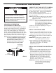
Installation Instructions
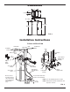
TYPICAL INSTALLATION
FIG. 9
Inlet
Outlet
Clips
Pipes
To Outside
Faucets
1” NPT Sweat
Adaptors (not
included)
Single
Bypass Valve
Lubricated
O-rings
Conditioned
Water
Hard Water
Main Water Pipe
Water Softener
Valve
Valve Drain
Elbow
Valve Drain
Hose*
*Do not connect
the water softener
valve drain tubing
to the salt storage
tank overflow
hose.
Floor Drain
Overflow
Drain Elbow
Salt Storage
Tank Overflow
Hose*
Secure Valve Drain Hose
in place over Floor Drain
NOTE: See “Air Gap Requirements” section.
NOTE: Water Softener shown with Salt Lid and
Top Cover removed
1-1/2”
air gap
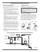
Dimensions
FIG. 8
35”
43-5/16”
3-3/8”
36-1/2”
OUT
IN
18”
19”
IN – OUT
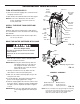
Plug-in
Power
Supply
To
Controller