
Installation Guide


10
Installation Instructions
COMPLETE INLET AND OUTLET PLUMBING
Measure, cut, and loosely assemble pipe and fittings
from the main water pipe to the inlet and outlet ports of
t
he water conditioner valve. Be sure to keep fittings
fully together, and pipes squared and straight.
Be sure hard water supply pipe goes to the water condi-
tioner valve inlet side.
NOTE: Inlet and outlet are marked on the water condi-
tioner valve. Trace the water flow direction to be
sure hard water is to inlet.
IMPORTANT: Be sure to fit, align and support all plumb-
ing to prevent putting stress on the water
conditioner valve inlet and outlet. Stress
from misaligned or unsupported plumbing
may cause damage to the valve.
Complete the inlet and outlet plumbing for the type of
pipe you will be using.
INSTALL VALVE DRAIN HOSE
1. Measure, cut to needed length and connect the 3/8"
drain line (provided) to the water conditioner valve
drain fitting. Use a hose clamp to hold the hose in
place.
NOTE: Make the valve drain line as short and direct as
possible.
IMPORTANT: If codes require a rigid drain line see
“Valve Drain requirements" section.
2. Route the drain hose or copper tubing to the floor
drain. Secure drain hose. This will prevent “whip-
ping'' during regenerations. See “Air Gap
Requirements" section.
1. Measure, cut to needed length and connect the 3/8"
drain line (provided) to the salt storage tank over-
flow elbow and secure in place with a hose clamp.
2 Route the hose to the floor drain, or other suitable
drain point no higher than the drain fitting on the salt
storage tank (This is a gravity drain). If the tank
overfills with water, the excess water flows to the
drain point. Cut the drain line to the desired length
and route it neatly out of the way.
IMPORTANT: For proper operation of the water condi-
tioner, do not connect the water condi-
tioner valve drain tubing to the salt stor-
age tank overflow hose.
INSTALL SALT STORAGE TANK OVERFLOW
HOSE
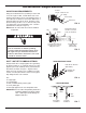
FIG. 13
Ground Wire
(not included)
Clamp
(2 - not included)
GROUNDING INFORMATION
(for Installations on Metal Pipe)
The house main incoming water pipe is often used to
ground electrical outlets in the home. Grounding pro-
tects you from electrical shock. Installing the water
conditioner with a plastic bypass valve will break this
ground. Before beginning installation, purchase and
securely install two grounding clamps and a #4 copper
wire across the location where the conditioner will be,
tightly clamping it at both ends, as shown in Figure 13.
NOTE: Check local plumbing and electrical codes for
proper installation of the ground wire. The
installation must conform to them. In
Massachusetts, plumbing codes of
Massachusetts shall be conformed to.
Consult with your licensed plumber.
Electrical Shock Hazard
Prior to installation on metallic plumbing,
securely install two grounding clamps and a
#4 copper wire per installation instructions.
Failure to follow these instructions can result
in death or electrical shock.