
Specifications


4
REFRIGERANT LINES
Use only refrigerant-grade (dehydrated and sealed) copper
tubing to connect the heat pump with the indoor evaporator. After
cutting the tubing, install plugs to keep refrigerant tubing clean
and dry prior to and during installation. Tubing should always be
cut square, keeping the ends round and free from burrs. Clean
the tubing to prevent contamination.
NOTE: Do not let the refrigerant lines come in direct contact with
plumbing, ductwork, floor joists, wall studs, floors and walls.
When running refrigerant lines through a foundation or wall,
openings should allow for sound and vibration absorbing material
to be placed or installed between tubing and foundation. Any gap
between the foundation or wall and refrigerant lines should be
filled with a pliable silicon-based caulk, RTV or a vibration
damping material. Avoid suspending refrigerant tubing from joists
and studs with rigid wire or straps that would come in contact
with the tubing. Use an insulated or suspension-type hanger.
Keep both lines separate and always insulate the suction line.
These sizes are recommended for line lengths of 79 ft (24 m) or
less to obtain optimum performance. For alternate line sizing
options or runs of more than 79 ft (24 m), refer to Remote Cooling
Service Manual, TP-107 Long Line Set Application R- 410A or
contact your distributor for assistance.
*For lines greater than 79 ft (24 m) in length or vertical elevation
changes more than 50 ft (15 m), refer to the Remote Cooling
Service Manual or contact your distributor for assistance.
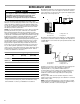
Mounting the evaporator coil above the heat pump will require an
inverted loop in the suction line adjacent or near the connection
to the evaporator coil. The top of the loop must be slightly higher
than the top of the evaporator coil.
Mounting the heat pump above the evaporator coil will require an
oil trap in the suction line. Install one oil trap at the evaporator for
a height difference of more than 15 ft (4.5 m) between indoor and
outdoor units.
Insulation is necessary to avoid condensation from forming and
dropping from the suction line. Armaflex (or satisfactory
equivalent) with ³⁄₈" (1 cm) minimum wall thickness is
recommended. In severe conditions (hot, high humidity areas),
¹⁄₂" (1.3 cm) insulation may be required. Insulation must be
installed in a manner which keeps tubing from damage and
contamination.
Where possible, drain as much residual compressor oil from
existing systems, lines and traps; pay close attention to low areas
where oil may collect.
NOTE: If changing refrigerant types, ensure the indoor coil and
metering device is compatible with the type of refrigerant being
used; otherwise, the indoor coil must be replaced.
Recommended Interconnecting Tubing—ft (m)
0 to 24
(7)
25 to 49
(8 to 15)
50 to 79
(15 to 24)*
Conditioner Line Diameter (in. OD)
Unit Tons Suction Liquid Suction Liquid Suction Liquid
1¹⁄₂ ⁵⁄₈ ¹⁄₄ ³⁄₄ ³⁄₈ ³⁄₄ ³⁄₈
2 ⁵⁄₈ ¹⁄₄ ³⁄₄ ³⁄₈ ³⁄₄ ³⁄₈
2¹⁄₂ ⁵⁄₈ ¹⁄₄ ³⁄₄ ³⁄₈ ⁷⁄₈ ³⁄₈
3 ³⁄₄ ³⁄₈ ⁷⁄₈ ³⁄₈ 1¹⁄₈ ³⁄₈
3¹⁄₂ ⁷⁄₈ ³⁄₈ 1¹⁄₈ ³⁄₈ 1¹⁄₈ ³⁄₈
4 ⁷⁄₈ ³⁄₈ 1¹⁄₈ ³⁄₈ 1¹⁄₈ ³⁄₈
5 ⁷⁄₈ ³⁄₈ 1¹⁄₈ ³⁄₈ 1¹⁄₈ ³⁄₈
Goodman 16
The compressor POE oil for R-410A units is extremely
susceptible to moisture absorption and could cause
compressor failure. Do not leave system open to
atmosphere any longer than necessary for installation.
CAUTION
A. Heat pump
B. Suction line
C. Evaporator coil
D. Liquid line
A. Heat pump
B. Liquid line
C. Suction line
D. Evaporator coil
A
B
C
D
A
B
C
D