
Specifications


6
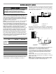
■ If the pressure rises to 1,000 microns or less and remains
steady, the system is considered leak-free; proceed to
start-up.
■ If pressure rises above 1,000 microns but holds steady
below 2,000 microns, moisture and/or noncondensibles
may be present or the system may have a small leak.
Return to Step 2: If the same result is encountered, check
for leaks as previously indicated and repair as necessary,
and then repeat evacuation.
■ If pressure rises above 2,000 microns, a leak is present.
Check for leaks as previously indicated and repair as
necessary, and then repeat evacuation.
ELECTRICAL CONNECTIONS
The unit rating plate lists pertinent electrical data necessary for
proper electrical service and over-current protection. Wires
should be sized to limit voltage drop to 2% (maximum) from the
main breaker or fuse panel to the unit.
Consult the NEC, CEC and all local codes to determine the
correct wire gauge and length.
Local codes often require a disconnect switch located near the
unit; do not install the switch on the unit. Refer to the installation
instructions supplied with the indoor furnace/air handler for
specific wiring connections and indoor unit configuration.
Likewise, consult the instructions packaged with the thermostat
for mounting and location information.
Over-current Protection
The following over-current protection devices are approved for
use.
■ Time-delay fuses
■ HACR-type circuit breakers
These devices have sufficient time delay to permit the motor
compressor to start and accelerate its load.
High Voltage Connections
Route power supply and ground wires through the high-voltage
port and terminate in accordance with the wiring diagram
provided inside the control panel cover.
Low Voltage Connections
The indoor transformer must supply 24-volt AC low-voltage
power to the outdoor section for the control wiring. Cooling only
units require 25VA minimum, and heat pump units require 40VA
minimum. Low voltage wiring for 2-stage units depends on the
thermostat used and the number of control wires between the
indoor unit and the heat pump. Route the control wires through
the low voltage port and terminate in accordance with the wiring
diagram provided inside the control panel cover.
5,000
4,500
4,000
3,500
3,000
2,500
2,000
1,500
1,000
500
0 1 2 3 4 5 6 7 8 9
10
Leak(s)
Present
Minutes
Vacuum in Microns
Condensibles or
small leak present
No leaks
No condensibles
Goodman 21
HIGH VOLTAGE!
WARNING
Disconnect ALL power before servicing.
Multiple power sources may be present.
Failure to do so may cause property damage,
personal injury or death due to electric shock.
Wiring must conform with NEC or CEC and all
local codes. Undersized wires could cause
poor equipment performance, equipment damage
or fire.
Goodman 22
To avoid the risk of fire or equipment damage, use
copper conductors.
WARNING
Goodman 23
Units with reciprocating or rotary compressors and
non-bleed TXV’s require a Hard Start Kit.
NOTICE