
Specifications


7
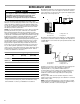
System Composite Diagram—Heat Pumps 10 KW and Below
System Composite Diagram—Heat Pumps Above 10 KW
NOTES:
EHR—Emergency Heat Relay (optional)
1. Outdoor thermostat (OT-1) should be the first to close and the
last to open.
2. Connect the white wires and brown wires from the air handler
together if OT-2 is not used.
3. Remove the wire when using the outdoor thermostat.
4. Terminal block markings.
NOTE: For 2-stage units, refer to the Installation Instructions
supplied with the variable-speed indoor units for field wiring
connections.
C
W2
O
Y
R
R
BR
G
W
R
Y
W
Y
O
C
W2
G
RE
R
G
W2
C
Heat Pump
Conventional
Room Thermostat
#18 Gauge - 7 Wire
Indoor Unit
Red
Green
White
Blue
BU
#18 Gauge - 5 Wire
BU
OR
See
Note 3
Outdoor Thermostat (Optional) Closed on Temperature Fall
#18 Gauge - 6 Wire Needed When Outdoor Thermostat Is Used
BU W OR Y R
See
Note 4
BU
W
G
R
C
W2
O
YR
R
Y
W
W
1
2
3
4
G
YOC GR
E
R
W2
BR
R
G
W2
C
Red
Green
White
Blue
See
Note 4
BU
W
G
R
W3
Brown
BR
Heat Pump
Conventional
Room Thermostat
#18 Gauge - 7 Wire
Indoor Unit
Outdoor Thermostat - 2
Outdoor Thermostat - 1
#18 Gauge - 5 Wire
BU
BU
OR
EHR
See
Note 3
See
Note 2
See Note 1
BU W OR Y R
Outdoor Thermostat (Optional) Closed on Temperature Fall
#18 Gauge - 7 Wire Needed When 2 Outdoor Thermostats Are Used
Symbol Color Symbol Color
RRedYYellow
BU Blue G Green
BR Brown W White
OR Orange