
Installation guide
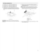
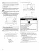

NOTE:Ifnowallstudsexistwithinthecabinetopening,donot 1. Usingastudfinder,locatetheedgesofthewallstud(s)within
installthemicrowaveoven. theopening.
Seeillustrationsin"PossibleWallStudConfigurations." 2. Markthecenterofeachstud,anddrawaplumblinedown
eachstudcenter.Seeillustrationsin"PossibleWallStud
Configurations."
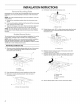
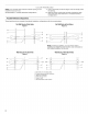
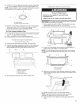
Possible Wall Stud Configurations
These depictions show examples of preferred installation configurations with the mounting plate.
No Wall Studs at End Holes
Figure 1
No Wall Studs at End Holes
Figure2
_i _
B
c................................Ljl
i
i
i
i
i
i
i
i
II'
i
C ! "
i !
J i C
D B ! "_
i
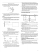
NOTE: If wall stud is within 6" (15.2 cm) of the vertical
centerline (see "Mark Rear Wall" section), only recirculation or
roof venting installation can be done.
B
Wall Stud at One End Hole
Figure3
_il i _i _
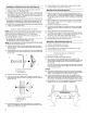
D
Wall Studs at Both End Holes
Figure4
_ ! _i _
_!_, ! _i _
F
i
i
i
A. End holes (on mounting plate)
B. Cabinet opening vertical centerline
C. Waft stud centerlines
D. Holes for lag screws
E. Support tabs
F. Mounting plate center markers
6