
Use and Care Manual
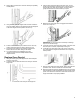
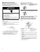
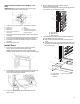
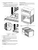
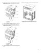
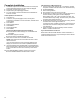
Table Of Contents
- BUILT-IN MICROWAVE/OVEN COMBO SAFETY
- Built-In Microwave/Oven Combination Safety
- MICROWAVE OVEN MAINTENANCE AND CARE
- General Cleaning
- Self-Cleaning Cycle
- Steam Clean (On Some Models)
- INSTALLATION INSTRUCTIONS
- REQUIREMENTS
- Tools and Parts
- Location Requirements
- Electrical Requirements
- INSTALLATIONS
- Prepare Built-In Oven
- Remove Oven Door(s)
- Replace Oven Door(s)
- Make Electrical Connection
- Install Oven
- Complete Installation
- SECURITE DE L'ENSEMBLE FOUR ELECTRIQUE/FOUR A MICRO-ONDES ENCASTRE
- Sécurité de l’ensemble four électrique/four à micro-ondes encastré
- ENTRETIEN ET REPARATION DU FOUR A MICRO-ONDES
- Nettoyage général
- Programme d’autonettoyage
- Steam Clean (nettoyage à la vapeur) (sur certains modèles)
- INSTRUCTIONS D'INSTALLATION
- SPECIFICATIONS
- Outils et pièces
- Exigences d’emplacement
- Spécifications électriques
- INSTALLATION
- Préparer le four encastré
- Enlever la/les porte(s) du four
- Réinstallation de la/des porte(s) du four
- Raccordement électrique
- Installation du four
- Achever l’installation
- SEGURIDAD DE LA COMBINACION DE HORNO DE MICROONDAS/HORNO INTEGRADO
- Seguridad de la combinación de horno de microondas/horno integrado
- MANTENIMIENTO Y CUIDADO DEL HORNO MICROONDAS
- Limpieza general
- Ciclo de autolimpieza
- Steam Clean (Limpieza con vapor) (en algunos modelos)
- INSTRUCCIONES DE INSTALACION
- REQUISITOS
- Herramientas y piezas
- Requisitos de ubicación
- Requisitos eléctricos
- INSTALACIONES
- Preparación del horno empotrado
- Retire las puertas del horno
- Vuelva a colocar las puertas del horno
- Hacer la conexión eléctrica
- Para instalar el horno
- Finalización de la instalación

14
6. After the bottom vent shield is installed.
� Align the bottom vent trim tab (B) with the oven frame (A)
as shown.
� Using one #8-18 x 3/8" (9.5 mm) screw (C) on each side of
the bottom vent trim tab (B), align the top of the bottom
vent trim tab (B) to the Hinge receiver (D) as shown.
� Fasten the bottom vent trim securely to the oven frame (A).
A. Oven frame
B. Bottom vent
trim tab
C. #8-18 x 3/8" (9.5 mm)
screw
D. Hinge receiver
7. Replace the oven racks.
8. Replace the oven door. See the “Replace Oven Door(s)”
section.
9. Check that the door is free to open and close. If it is not,
repeat the removal and installation procedures. See the
“Prepare Built-In Oven” section.
10. Repeat for lower oven door.
IMPORTANT: For proper oven operation, check that the gap
between bottom trim of the door and bottom vent trim is at least
1/4" (6.4 mm).
11. Reconnect power.
12. The display panel will light briefly, and “PF” should appear in
the display.
13. If the display panel does not light, refer the Warranty.
Positioning Oven Feet
The oven feet need to be installed to allow a microwave/oven
combination to be installed in a recommended cutout height of
42
1
/
2
" (107.9 cm).
NOTE: Do not remove the spacers.
A. Spacers
1. Using 2 or more people, place the on its back on a covered
surface.
A
C
B
D
B