
Installation manual


9
OPERATION
Start-up Procedure and Checklist—Cool
1. Disconnect power at all disconnects.
2. Turn the thermostat system switch to “COOL” and the fan
switch to “AUTO.”
3. Turn the temperature setting to the highest setting.
4. Inspect all of the registers and set them to the normal open
position.
5. Turn on the electrical supply at the disconnect.
6. Turn the fan switch to the “ON” position. The blower should
operate after a 7-second delay.
7. Turn the fan switch to the “AUTO” position. The blower
should stop after a 65-second delay.
8. Slowly lower the cooling temperature until the unit starts. The
compressor, blower and fan should now be operating.
9. Allow the unit to run for 10 minutes. Make sure that cool air is
being supplied by the unit.
10. Turn the temperature setting to the highest position, stopping
the unit. The indoor blower will continue to run for
65 seconds.
11. Turn the thermostat system switch to “OFF” and disconnect
all power when servicing the unit.
Start-up Procedure and Checklist—Heat Pump
1. Check that the cooling mode for the heat pump is working
properly according to the procedure listed in the “Start-up
Procedure and Checklist—Cooling Cycle” section.
■ The reversing valve is energized when the thermostat is
placed in the cooling position.
■ A clicking sound should be noticeable from the reversing
valve.
■ By lowering the temperature setting to call for cooling, the
contactor is energized.
■ The compressor, blower and fan should then be running.
2. After the cooling mode is checked out, turn the thermostat
system switch to “OFF.”
3. Turn the thermostat switch to “HEAT” and the fan switch to
“AUTO.”
4. Slowly raise the heating temperature setting. When the
heating 1
st
stage makes contact, stop raising the temperature
setting. The compressor, blower and fan should now be
running with the reversing valve in the de-energized (heating)
position.
5. After giving the unit time to settle out, make sure that the unit
is supplying heated air.
6. If the outdoor ambient is above 80°F (26.7ºC), the unit may
trip on its high pressure cutout when on heating. The
compressor should stop.
IMPORTANT: The heating cycle must be thoroughly checked, so
postpone the test to another day when conditions are more
suitable. Do not fail to test the unit.
7. If the outdoor ambient is low and the unit operates properly
on the heating cycle, you may check the pressure cutout
operation by blocking off the indoor return air until the unit
trips.
8. If the unit operates properly in the heating cycle, raise the
temperature setting until the heating 2
nd
stage makes contact.
Supplemental resistance heat, if installed, should now turn
on. Make sure that the supplemental resistant heat operates
properly.
NOTE: If outdoor thermostats are installed, the outdoor
ambient temperature must be below the set point of these
thermostats for the heaters to operate. It may be necessary
to jumper these thermostats to check heater operation if
outdoor ambient temperature is mild.
9. For thermostats with an emergency heat switch, return to
Step 4.
NOTE: The emergency heat switch is located at the bottom
of the thermostat. Move the switch to emergency heat. The
heat pump will stop, the blower will continue to run, all
heaters will come on and the thermostat emergency heat light
will turn on. All 3-phase models are single-stage heat only.
10. If you are checking the unit in the wintertime when the
outdoor coil is cold enough to activate the defrost control,
observe at least one defrost cycle to make sure the unit
defrosts completely.
Goodman 6
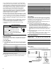
HIGH VOLTAGE!
WARNING
Disconnect ALL power before servicing.
Multiple power sources may be present.
Failure to do so may cause property damage,
personal injury or death.
Goodman 6
HIGH VOLTAGE!
WARNING
Disconnect ALL power before servicing.
Multiple power sources may be present.
Failure to do so may cause property damage,
personal injury or death.