80% 2-STAGE VARIABLE SPEED GAS FURNACE INSTALLATION INSTRUCTIONS ATTENTION INSTALLATION PERSONNEL As a professional installer, you have an obligation to know the product better than the customer. This includes all safety precautions and related items. Prior to actual installation, thoroughly familiarize yourself with this instruction manual. Pay special attention to all safety warnings.
TABLE OF CONTENTS GAS FURNACE SAFETY PRECAUTIONS ....................................3 Additional Safety Considerations.................................................4 PRODUCT DESCRIPTION AND APPLICATION ..........................4 Shipping Inspection .....................................................................4 Electrostatic Discharge (ESD) Precautions..................................4 To the Installer..............................................................................
GAS FURNACE SAFETY PRECAUTIONS Please adhere to the following warnings and cautions when installing, adjusting, altering, servicing or operating the furnace. To ensure proper installation and operation, thoroughly read this manual for specifics pertaining to the installation and application of this product. Recognize this symbol as a safety precaution. WARNING Hazards or unsafe practices1could result in property Goodman damage, product damage, severe personal injury or death.
WARNING Goodman 46 To prevent possible property damage, personal injury or death due to electrical shock, the furnace must be located to protect the electrical components from water. WARNING Goodman 43 Should overheating occur or the gas supply fail to shut off, turn off the manual gas shutoff valve external to the furnace before turning off the electrical supply.
The vent system is permanently installed according to these installation instructions. ■ A room thermostat is used to control the furnace. Fixed jumpers that provide continuous heating cannot be used. ■ Return air ducts are provided and sealed to the furnace. ■ A return air temperature range between 60ºF and 80ºF (16ºC and 27ºC) is maintained. ■ Air filters are installed in the system and maintained during construction, replaced as appropriate during construction and upon completion of construction.
The rated heating capacity of the furnace should be greater than or equal to the total heat loss of the area to be heated. The total heat loss should be calculated by an approved method or in accordance with “ASHRAE Guide” or “Manual J-Load Calculations” published by the Air Conditioning Contractors of America. In the U.S.A., this furnace must be installed in accordance with the latest edition of the ANSI Z223.
Counterflow Installation Over a Noncombustible Floor ■ Before setting the furnace over the plenum opening, ensure that the surface around the opening is smooth and level. A tight seal should be made between the furnace base and floor by using a silicone rubber caulking compound or cement grout. Counterflow Installation Over a Combustible Floor ■ If installation over a combustible floor becomes necessary, use an accessory subbase (see Specification Sheet applicable for your model for details).
Existing Furnace Removal NOTE: When an existing furnace is removed from a venting system serving other appliances, the venting system may be too large to properly vent the remaining attached appliances. The following vent testing procedure is reproduced from the American National Standard/National Standard of Canada for Gas-Fired Central Furnaces ANSI Z21.47—latest edition, CSA-2.3 latest edition Section 1.23.1.
All installations must be vented in accordance with National Fuel Gas Code NFPA 54/ANSI Z223.1—latest edition. In Canada, the furnaces must be vented in accordance with the National Standard of Canada, CAN/CSA B149.1 and CAN/CSA B149.2— latest editions and amendments. NOTE: The vertical height of the Category I venting system must be at least as great as the horizontal length of the venting system.
WARNING Checklist Summary Possiblility of property damage, personal injury or death. Damaging condensation can occur inside masonry Goodman 69 Category I appliance chimneys when a single fan-assisted (80% AFUE furnace) is vented without adequate dilution air. Do not connect an 80% furnace to a masonry chimney unless the furnace is common vented with a draft hood equipped appliance or the chimney is lined with a metal liner or Type B metal vent.
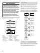
If the chimney does not meet these termination requirements, but all other requirements in the checklist can be met, it may be possible for a mason to extend the chimney. If this will not be practical, see “Fix 1—Liner Termination.” Termination 10 ft (3 m) or Less From Ridge, Wall or Parapet A B Solid fuel appliances include fireplaces, wood stoves, coal furnaces and incinerators. Liquid fuel appliances include oil furnaces, oil-fired boilers and oil-fired water heaters.
Flexible liners should be hung straight or nearly straight. If it is spiraled in the chimney and in good condition, it should be rehung. To do this, break the top seal. Pull up and cut off the excess liner length and refit the top seal. Use caution when doing this, since the cut edges of flexible liners may be sharp. The surfaces of the liner must be physically sound. If gaps or holes are present, the metal liner must be removed and replaced (Fix 4—Relining).
If a flexible liner is to be used, it must be made of the proper materials, such as: ■ For most residential applications, an aluminum liner should be acceptable. ■ If the combustion air supplied to the furnace will be contaminated with compounds containing chlorine or fluorine, a liner of AL 29-4C stainless steel should be used.
To make electrical connections through the opposite side of the furnace, the junction box must be relocated to the other side of the burner or blower compartment prior to making electrical connections. To relocate the junction box, follow the steps shown in “Junction Box Relocation.” NOTE: Wire routing must not to interfere with circulator blower operation, filter removal or routine maintenance. Junction Box Relocation Goodman 56 WARNING Edges of sheet metal holes may be sharp.
NOTES: ■ For single-stage cooling applications, a jumper may be required between Y1 and Y2 at the furnace control in order to achieve the desired single-stage cooling airflow. Consult the Blower Performance charts to determine if the required single-stage cooling airflow can be delivered at low stage (Y1 input) or high stage (Y2 input). Additionally, use of ramping profile and dehumidification features require a jumper between Y1 and O and Y1 and DEHUM, respectively.
24-Volt Dehumidistat Wiring The optional usage of a dehumidistat allows the furnace’s circulator blower to operate at a slightly lower speed (82% of desired speed) during a combined thermostat call for cooling and dehumidistat call for dehumidification. This can be done through an independent dehumidistat or through a thermostat’s DEHUM terminal (if available). This lower blower speed enhances dehumidification of the conditioned air as it passes through the AC coil.
If it is necessary for the installer to supply additional line voltage wiring to the inside of the furnace, the wiring must conform to all local codes, and have a minimum temperature rating of 105°C. All line voltage wire splices must be made inside the furnace junction box. The integrated control module humidifier terminals (HUM) are energized with 115 volts whenever the induced draft blower is energized.
Gas Piping Connections ■ CAUTION To avoid possible unsatisfactory operation or equipment damage due to underfiring of equipment, use the proper size of Natural/propane gas piping Goodman 62needed when running pipe from the meter/tank to the furnace. When sizing a trunk line, be sure to include all appliances which will operate simultaneously. The gas piping supplying the furnace must be properly sized based on the gas flow required, specific gravity of the gas and the length of the run.
Drip leg Manual shutoff valve ■ Transition piece from ¹⁄₂" to another pipe size, if needed When the gas piping enters through the left side of the furnace, the installer must supply the following fittings (starting from the gas control valve): ■ Straight pipe to reach the exterior of the furnace ■ Ground joint union ■ Drip leg ■ Manual shutoff valve ■ Transition piece from ¹⁄₂" to another pipe size, if needed ■ Propane Gas Tanks and Piping ■ Counterflow Installations When the gas piping enters through th
Sizing Between 1st and 2nd Stage Regulator* Maximum propane capacities listed are based on 2 psig pressure drop at 10 psig setting. Capacities in 1,000 Btu/h. Propane Gas Piping Chart I Tubing Size, O.D. Type L Nominal Pipe Size Schedule 40 Pipe or Tubing Length—ft (m) ³⁄₈" ¹⁄₂" ⁵⁄₈" ³⁄₄" ⁷⁄₈" ¹⁄₂" ³⁄₄" 10 (3) 730 1,700 3,200 5,300 8,300 3,200 7,500 20 (6.1) 500 1,100 2,200 3,700 5,800 2,200 4,200 30 (9.2) 400 920 2,000 2,900 4,700 1,800 4,000 40 (12.
CIRCULATING AIR AND FILTERS Ductwork—Airflow WARNING Goodman 68of combustion, including carbon Never allow the products monoxide, to enter the return ductwork or circulation air supply. Duct systems and register sizes must be properly designed for the CFM and external static pressure rating of the furnace. Design the ductwork in accordance with the recommended methods of “Air Conditioning Contractors of America” Manual D.
START-UP PROCEDURE AND ADJUSTMENT This furnace must have a 115 VAC power supply properly connected and grounded. Proper polarity must be maintained for correct operation. In addition to the following start-up and adjustment items, refer to further information in “Operational Checks.” 2. Remove the burner compartment door and move the furnace gas control valve manual control to the Off position. 3. Close the manual gas shutoff valve external to the furnace. 4. Replace the burner compartment door.
Gas Control Valve—Honeywell 2-Stage VR9205 A 5. Measure the furnace gas supply pressure with burners firing. NOTE: Supply pressure must be within the range specified in the Inlet Gas Supply Pressure chart. B Inlet Gas Supply Pressure F C D E A. Regulator vent B. High-fire regulator adjust C. Outlet D. Low-fire regulator adjust E. On/Off selector switch F. Inlet Gas Control Valve—Honeywell VR9205 Connected to Manometer C B A Natural Gas Minimum: 5.0" W.C. Maximum: 10.0" W.C.
3. Outlet pressure tap connections: ■ Honeywell VR9205 valve: Remove the outlet pressure boss plug. Install an ¹⁄₈" NPT hose barb fitting into the outlet pressure tap. ■ White-Rodgers 36G54 valve: Back outlet pressure test screw (inlet/outlet pressure boss) out one turn counterclockwise (not more than one turn). 4. Attach a hose and manometer to the outlet pressure barb fitting (Honeywell valve) or outlet pressure boss (White-Rodgers valve). 5. Turn on the gas supply. 6.
Temperature Rise Measurement Rise = Supply air temperature - Return air temperature A B C D E A. Heat exchanger radiation C. Supply air temperature “line of sight” D. Return air temperature B. Supply air E. Return air 4. Subtract the return air temperature from the supply air temperature to determine the air temperature rise. Allow adequate time for thermometer readings to stabilize. 5. Adjust the temperature rise by adjusting the circulator blower speed.
Speed Taps—Adjust Provides a 1-minute Off delay at 100% of the cooling demand airflow. ■ Switch Bank: S3 DIP Switch Number Adjust Tap 3 4 Normal* Off Off +10% Adjust On Off -10% Adjust Off On Normal On On Profile D ■ ■ The multispeed circulator blower also offers several custom On/ Off ramping profiles. These profiles may be used to enhance the cooling performance and increase the comfort level. The ramping profiles are selected using DIP switches 5 and 6.
To Set Airflow Blower Heat Off Delay Timings 1. 2. 3. 4. 5. 6. 7. Select the model and desired high-stage cooling airflow. Determine the corresponding tap (A, B, C, or D). Set DIP switches 1 and 2 to the appropriate On/Off positions. Select the model and desired high-stage heating airflow. Determine the corresponding tap (A, B, C, or D). Set DIP switches 7 and 8 to the appropriate On/Off positions. Select the airflow adjustment factor taps (A and D are 1; Tap B is +10; Tap C -10). 8.
■ ■ ■ ■ ■ ■ ■ ■ ■ ■ ■ ■ ■ If the thermostat call is for low heat, the gas control valve and induced draft blower will continue on low stage. If the call is for high heat, the gas control valve and induced draft blower will change to high stage. Circulator blower is energized on heat speed following a fixed 30-second blower-on delay. The circulator blower requires 30 seconds to ramp up to full speed. Electronic air cleaner terminal is energized with circulator blower.
■ Primary Limit Control The primary limit control is located on the partition panel and monitors heat exchanger compartment temperatures. It is a normally closed (electrically), automatic reset, temperatureactivated sensor. The limit guards against overheating as a result of insufficient conditioned air passing over the heat exchanger. ■ ■ ■ Auxiliary Limit Controls The auxiliary limit controls are located on or near the circulator blower and monitors blower compartment temperatures.
Burners WARNING To avoid personal injury or death due to electrical shock, do not remove any internal compartment covers or attempt any adjustment. Contact a qualified servicer at once if an abnormal flame should develop. Visually inspect the burner flames periodically during the heating season. Turn on the furnace at the thermostat and allow several minutes for flames to stabilize, since any dislodged dust will alter the flames normal appearance.
TROUBLESHOOTING Electrostatic Discharge (ESD) Precautions Fault Recall NOTE: Discharge static electricity accumulated in the body before touching the unit. An electrostatic discharge can adversely affect electrical components. Use the following steps during furnace installations and servicing to protect the integrated control module from damage.
Diagnostic Chart WARNING Goodman 118 Long HIGH VOLTAGE! To avoid personal injury or death due to electrical shock, disconnect electrical power before performing any service or maintenance. The dual 7-segment LED display will display an error code that may contain a letter and number. The error code may be used to assist in troubleshooting the unit. Symptoms of Abnormal Operation ■ ■ Furnace fails to operate. Integrated control module diagnostic LED display provides no signal.
Symptoms of Abnormal Operation ■ ■ ■ ■ Diagnostic/ Status LED Code Fault Description Possible Causes Furnace fails to operate. Integrated control module LED display provides “E1” error code. E1 Induced draft blower runs continuously with no further furnace operation. Integrated control module LED display provides “E2” error code. E2 ■ ■ Low-stage pressure switch circuit is closed at start of heating cycle. ■ Low-stage pressure switch circuit is not closed.
Symptoms of Abnormal Operation ■ ■ ■ ■ ■ ■ ■ ■ ■ 34 Diagnostic/ Status LED Code Fault Description Possible Causes No furnace operation. Integrated control module LED display provides “E5” error code. E5 Furnace not operating. Integrated control module LED display provides “E6” error code. E6 ■ ■ Open fuse. Flame sense microamp signal is low.
Symptoms of Abnormal Operation ■ ■ Furnace fails to operate on high stage. Furnace operates normally on low stage. Integrated control module LED display provides “E9” error code. Diagnostic/ Status LED Code Fault Description Possible Causes E9 ■ ■ ■ High-stage pressure switch circuit is not closed. Induced draft blower is operating. Furnace is operating on low stage only. ■ ■ ■ ■ ■ ■ ■ ■ Furnace fails to operate. Integrated control module LED display provides “EA” error code.
Symptoms of Abnormal Operation ■ ■ Furnace fails to operate. Integrated control module LED display provides “b0” error code. Diagnostic/ Status LED Code Fault Description Possible Causes b0 ■ Circulator blower motor is not running when it should be running. ■ ■ ■ ■ ■ ■ ■ Furnace fails to operate. Integrated control module LED display provides “b1” error code. b1 Furnace fails to operate. Integrated control module LED display provides “b2” error code.
Symptoms of Abnormal Operation ■ ■ ■ ■ ■ ■ ■ ■ Furnace fails to operate. Integrated control module LED display provides “b4” error code. Diagnostic/ Status LED Code Fault Description Possible Causes b4 ■ ■ Furnace fails to operate. Integrated control module LED display provides “b5” error code. b5 Furnace fails to operate. Integrated control module LED display provides “b6” error code. b6 Furnace fails to operate. Integrated control module LED display provides “b7” error code.
DIP Switch Chart Goodman 118 Long WARNING HIGH VOLTAGE! To avoid personal injury or death due to electrical shock, disconnect electrical power before performing any service or maintenance.
WIRING DIAGRAM WARNING Goodman 6 Long HIGH VOLTAGE! Disconnect ALL power before servicing. Multiple power sources may be present. Failure to do so may cause property damage, personal injury or death. GND Junction Box Induced Draft Blower 2-Stage Pressure Switch Assembly Equipment GND 24V Humidifier Field GND Hot Surface Igniter 2-Circuit 2 1 Connector Field Splice Switch Temp.) ( 2-Stage Gas Control Valve W Pressure Switch Overcurrent Prot.
ASSISTANCE OR SERVICE If you need further assistance, you can write to the below address with any questions or concerns: Tradewinds Distributing Company, LLC 14610 Breakers Drive Jacksonville, FL 32258 WPIO-369B © 2010. All rights reserved. Please include a daytime phone number in your correspondence. Or call toll free: 1-866-944-7575. ®Registered Trademark/TM Trademark of Whirlpool, U.S.A., Manufactured under license by Tradewinds Distributing Company, LLC, Jacksonville, Florida.