30" AND 36" (76.2 AND 91.4 CM) WALL-MOUNT CANOPY RANGE HOOD Installation Instructions and Use & Care Guide For questions about features, operation/performance, parts, accessories or service, call: 1-800-253-1301 or visit our website at www.whirlpool.com In Canada, call 1-800-807-6777 or visit our website at www.whirlpool.
TABLE OF CONTENTS TABLE DES MATIÈRES RANGE HOOD SAFETY..................................................................2 INSTALLATION REQUIREMENTS..................................................4 Tools and Parts..............................................................................4 Location Requirements.................................................................4 Venting Requirements...................................................................5 Electrical Requirements................
IMPORTANT SAFETY INSTRUCTIONS READ AND SAVE THESE INSTRUCTIONS 3
INSTALLATION REQUIREMENTS Tools and Parts Gather the required tools and parts before starting installation. Read and follow the instructions provided with any tools listed here. Tools Needed ■■ Level ■■ Drill with 11/4" (3.2 cm), 3/8" (9.5 mm), and 5/16" (7.
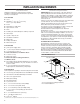
Cabinet Dimensions Venting Requirements 10" (25.4 cm) min. 13" (33.0 cm) max. (vented models only) 2" (5.1 cm) min. 9" (22.9 cm) min.* ■■ Vent system must terminate to the outdoors except for non-vented (recirculating) installations. ■■ Do not terminate the vent system in an attic or other enclosed area. ■■ Do not use 4" (10.2 cm) laundry-type wall cap. ■■ Use metal vent only. Rigid metal vent is recommended. Plastic or metal foil vent is not recommended. 9¹⁄₂" (24.
For Non-Vented (Recirculating) Installations If it is not possible to vent cooking fumes and vapors to the outside, the hood can be used in the non-vented (recirculating) version, using a Recirculation Kit (which includes charcoal filters and a deflector). To order, see the “Assistance or Service” section. Roof Venting A. Roof cap B. 6" (15.2 cm) round vent Wall Venting A. Wall cap B. 6" (15.2 cm) round vent Non-Vented (Recirculating) Electrical Requirements Observe all governing codes and ordinances.
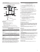
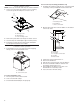
INSTALLATION INSTRUCTIONS Prepare Location ■■ It is recommended that the vent system be installed before hood is installed. ■■ Before making cutouts, make sure there is proper clearance within the ceiling or wall for exhaust vent. Check your ceiling height and the hood height maximum before you select your hood. 1. Disconnect power. 2. Determine which venting method to use: roof, wall, or non-vented. 3. Select a flat surface for assembling the range hood. Place covering over that surface.
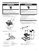
Install Range Hood NOTE: Remove protective film from range hood and metal filters. 1. Using 2 or more people, hang range hood on 2 mounting screws through the mounting slots on back of hood. For non-vented (recirculating) installation only: 1. Assemble the air deflector with the duct cover bracket with 4 assembly screws provided with the Recirculation Kit. A A B B C A. Assembly screws B. Air deflector C. Duct cover bracket 2.
Make Electrical Connection 6. Use UL listed wire connectors and connect white wires (C) together. WARNING WARNING Electrical Shock Hazard Electrical Shock Hazard Disconnect power before servicing. Electrically ground blower. Replace all parts and panels before operating. Connect ground wire to green and yellow ground wire in terminal box. Failure to do so can result in death or electrical shock. 1. Disconnect power. 2. Remove terminal box cover. 3.
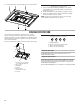
2. Secure the bottom of the duct with (2) 4.2 x 8 mm screws. Complete Installation 1. For non-vented (recirculating) installations only, install charcoal filters over metal grease filter. See the “Range Hood Care” section. 2. Install metal filters. See the “Range Hood Care” section. 3. Check the operation of the range hood blower and light. See the “Range Hood Use” section. NOTE: To get the most efficient use from your new range hood, read the “Range Hood Use” section.
RANGE HOOD CARE Cleaning IMPORTANT: Clean the hood and grease filters frequently according to the following instructions. Replace grease filters before operating hood. Exterior Surfaces To avoid damage to the exterior surface, do not use steel wool or soap-filled scouring pads. Always wipe dry to avoid water marks. Cleaning Method: ■■ Liquid detergent soap and water or all-purpose cleanser ■■ Wipe with damp soft cloth or nonabrasive sponge, and then rinse with clean water and wipe dry.
WIRING DIAGRAM L N Gnd Push Button Switch Operation YL BR WH BK BU YL/GN YL/GN WH BK Mechanical Push Buttons (4 buttons 3 speeds) EMI Filter BK BU WH BK RD WH WH BU BU YL YL BR BK GY WH POSITION Off No Connection Lamps Brown/Yellow (L-1) Low Speed Brown/White (L-2) Med Speed Brown/Blue (L-3) High Speed Brown/Black (L-4) BU YL YL/GN BK FUNCTION Motor Specifications BR YL WH BK RD Power Supply 120 VAC Frequency 60 Hz Power Absorption 240 W RD GY Input: 120
ASSISTANCE OR SERVICE In Canada If You Need Service Please refer to the warranty page in this manual. If You Need Replacement Parts If you need to order replacement parts, we recommend that you use only factory specified parts. Factory specified parts will fit right and work right because they are made with the same precision used to build every new appliance.
WHIRLPOOL® MAJOR APPLIANCE LIMITED WARRANTY ATTACH YOUR RECEIPT HERE. PROOF OF PURCHASE IS REQUIRED TO OBTAIN WARRANTY SERVICE. Please have the following information available when you call the Customer eXperience Center: ■■ Name, address and telephone number ■■ Model number and serial number ■■ A clear, detailed description of the problem ■■ Proof of purchase including dealer or retailer name and address IF YOU NEED SERVICE: 1.
SÉCURITÉ DE LA HOTTE DE CUISINIÈRE Votre sécurité et celle des autres est très importante. Nous donnons de nombreux messages de sécurité importants dans ce manuel et sur votre appareil ménager. Assurez-vous de toujours lire tous les messages de sécurité et de vous y conformer. Voici le symbole d’alerte de sécurité. Ce symbole d’alerte de sécurité vous signale les dangers potentiels de décès et de blessures graves à vous et à d’autres.
IMPORTANTES INSTRUCTIONS DE SÉCURITÉ AVERTISSEMENT : POUR RÉDUIRE LE RISQUE D'INCENDIE, CHOC ÉLECTRIQUE OU DOMMAGES CORPORELS, RESPECTER LES INSTRUCTIONS SUIVANTES : ■ Utiliser cet appareil uniquement dans les applications envisagées par le fabricant. Pour toute question, contacter le fabricant.
EXIGENCES D’INSTALLATION Outils et pièces ■■ 4 chevilles d’ancrage de 10 x 60 mm Rassembler les outils et pièces nécessaires avant d’entreprendre l’installation. Lire et observer les instructions fournies avec chacun des outils de la liste ci-dessous. ■■ Adaptateur T20® Torx®† Outils nécessaires IMPORTANT : Observer les dispositions de tous les codes et règlements en vigueur. Confier l'installation de la hotte à un technicien qualifié.
Dimensions du placard Exigences concernant l’évacuation 10" (25,4 cm) min. 13" (33,0 cm) max. 2" (5,1 cm) min. 9" (22,9 cm) min.* 9¹⁄₂" (24,1 cm) Point d'entrée du circuit d'évacuation et du câble d'alimentation électrique 10" (25,4 cm) min. 13" (33,0 cm) max.
La sortie à l'extérieur du circuit d'évacuation peut se faire à travers le toit ou à travers un mur. Pour la sortie à travers un mur, on doit employer un raccord coudé (90°). Exemple de circuit d'évacuation Coude à 90˚ 6 pi (1,8 m) Bouche de décharge murale Décharge par l'arrière Le raccord coudé à 90° peut être installé immédiatement au-dessus de la hotte.
INSTRUCTIONS D’INSTALLATION Préparation de l’emplacement ■■ Il est recommandé d’installer le circuit d’évacuation avant de procéder à l’installation de la hotte. ■■ Avant d’exécuter les découpages, vérifier la disponibilité d’un dégagement suffisant dans le plafond ou le mur pour le conduit d’évacuation. Avant de sélectionner la hotte à installer, mesurer la hauteur libre sous plafond et la hauteur maximum disponible sous la hotte. 1. Déconnecter la source de courant électrique. 2.
3. Acheminer le câble d’alimentation du domicile selon les prescriptions du Code national de l’électricité, des normes CSA et des codes et règlements locaux. Il faut que la longueur du conduit de 1/2" et des conducteurs soit suffisante depuis le tableau de distribution (avec fusibles ou disjoncteurs) pour réaliser le raccordement dans le boîtier de connexion de la hotte. REMARQUE : Ne pas mettre le système sous tension avant d’avoir complètement terminé l’installation. 4.
Raccordement électrique 4. Acheminer le cordon d’alimentation du domicile à travers le serre-câble, dans le boîtier de connexion. A B AVERTISSEMENT C Risque de choc électrique Déconnecter la source de courant électrique avant l'entretien. Replacer pièces et panneaux avant de faire la remise en marche. Le non-respect de ces instructions peut causer un décès ou un choc électrique. 1. Déconnecter la source de courant électrique. 2. Retirer le couvercle du boîtier de connexion. 3.
Installation des cache-conduits REMARQUE : Ôter le film de protection des couvercles de ventilation. 1. En cas d’utilisation des sections supérieure et inférieure du cache-conduit, pousser la section inférieure vers le bas, sur la hotte et soulever la section supérieure vers le plafond puis installer l'ensemble avec 2 vis de 4,2 x 8 mm. REMARQUE : Pour les installations avec décharge à l'extérieur, le cache-conduit supérieur peut être inversé pour dissimuler les fentes. 2.
ENTRETIEN DE LA HOTTE Nettoyage IMPORTANT : Nettoyer fréquemment la hotte et les filtres à graisse en suivant les instructions suivantes. Réinstaller les filtres à graisse avant de faire fonctionner la hotte. Surfaces externes Afin d'éviter d'endommager la surface externe, ne pas utiliser de tampons en laine d'acier ou de tampons à récurer savonneux. Toujours essuyer pour éviter de laisser des marques d'eau. Méthode de nettoyage : ■■ Savon détergent liquide et eau, ou produit de nettoyage polyvalent.
SCHÉMA DE CÂBLAGE Ph Neu Terre Fonctionnement du commutateur du bouton-poussoir JA MAR BL N BU JA/VE JA/VE BL Filtre EMI N BU BL N R BL BL BU BU JA JA MAR N GRIS BL POSITION Arrêt Pas de connexion Lampes Marron/Jaune (L-1) Vitesse basse Marron/Blanc (L-2) Vitesse moyenne Marron/Bleu (L-3) Vitesse élevée Marron/Noir (L-4) JA/VE N FONCTION BU JA Carateristiques du moteur MAR JA BL N R GRIS Entrée : 120 VAC JA/VE + Sortie : 700mA (2-15 VDC) - BU Pilot DEL Alimen
ASSISTANCE OU SERVICE Si vous avez besoin de service Pour plus d’assistance Consulter la page de garantie du présent manuel. Si vous avez besoin de plus d’assistance, vous pouvez soumettre par écrit toute question ou préoccupation à Whirlpool Canada à l’adresse suivante : Whirlpool Brand Home Appliances Customer eXperience Centre Whirlpool Canada 200 - 6750 Century Ave.
GARANTIE LIMITÉE DES GROS APPAREILS MÉNAGERS WHIRLPOOL® ATTACHEZ ICI VOTRE REÇU DE VENTE. UNE PREUVE D’ACHAT EST OBLIGATOIRE POUR OBTENIR L’APPLICATION DE LA GARANTIE.
CLAUSE D’EXONÉRATION DE RESPONSABILITÉ AU TITRE DES GARANTIES IMPLICITES LES GARANTIES IMPLICITES, Y COMPRIS LES GARANTIES APPLICABLES DE QUALITÉ MARCHANDE OU D’APTITUDE À UN USAGE PARTICULIER, SONT LIMITÉES À UN AN OU À LA PLUS COURTE PÉRIODE AUTORISÉE PAR LA LOI. Certains États et provinces ne permettent pas de limitation sur la durée des garanties implicites de qualité marchande ou d’aptitude à un usage particulier, de sorte que la limitation ci-dessus peut ne pas être applicable dans votre cas.