Installation G U I D E MODULAR ICE MAKER KIT 2181913E www.whirlpool.
Table of Contents REQUESTING ASSISTANCE OR SERVICE...................................2 IMPORTANT INFORMATION..........................................................3 BEFORE YOU BEGIN......................................................................4 Tools..............................................................................................4 Installation notes...........................................................................4 Components..................................................
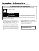
Important Information The following information is used throughout this Installation Guide. Read it carefully so you are familiar with it. Your safety and the safety of others are very important. We have provided many important safety messages in this manual and on your appliance. Always read and obey all safety messages. This is the safety alert symbol. This symbol alerts you to potential hazards that can kill or hurt you and others.
Before You Begin Tools Installation notes Gather required tools and parts before starting installation. Read and follow the instructions provided with any tools listed here. 1. Regular screwdriver 2. Phillips screwdriver 3. 7⁄16" and 1⁄2" open-end wrenches (or an adjustable wrench) 4. Pliers 5. 1⁄4" nut driver 6. Hand drill with 1⁄4" drill bit 7. Small hand level (optional) 8. Small 3⁄4-round file 9. Tubing cutter 10. Center punch 11. Hammer 12. Scissors 13. Ruler 14. Step stool (optional) 1.
Components Remove the contents from the shipping carton and set them on a table where they can be easily identified and located. Check all of the components in the kit against the following list to help you become familiar with them. When you identify a component, place a check mark ( 3) after it. The KEY numbers correspond to the “Component Illustrations.” IMPORTANT: When you remove the water valve and flexible tubing from the styrofoam packing insert, do not remove the tubing from the valve.
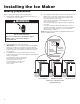
Installing the Ice Maker Making preparations 4. Refer to the illustration below for the following steps. 1. Gently pull the refrigerator away from the wall so that you can easily access the rear panel. On an appliance with a bottom freezer, remove the slide-out basket, the ice cube trays, and the wire ice cube holder (if necessary, refer to your “Use and Care Guide” for the procedure). Set these items aside. On top-mount models without a full-width freezer shelf, remove the ice tray shelf.
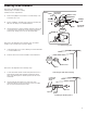
Side-by-side models Refer to the side diagram for the following steps. You will be working inside the freezer compartment. 1. 2. Remove the phillips screw from the ice maker wiring cover and remove the cover. Refer to DETAIL A, and with a pair of pliers, break away the tabs from the wiring cover and discard them. Hole Insert pin into hole Hole cover Pin Slot Wiring harness Tab 3.
Refer to the side diagram for the following step. You will be working inside the freezer compartment. 1. Install the plastic extension by sliding it over the fill tube as far as it will go. Fill tube Slot Wiring harness Long fill tube extension Installing the long fill tube extension Refer back to the side diagram for the following step. 2. Position the wiring harness so that it is through the slot in the wiring cover. Insert the tab at the back of the wiring cover into the freezer liner slot.
Top/bottom freezer models Refer to the side diagrams for the following 2 steps. You will be working inside the freezer compartment. 1. Mounting hole Snaps Cover Hex screw On models with a flat cover: Remove the screw from the ice maker wiring cover. Unhook the right side tab from the edge of the back cover. Remove ice maker wiring cover. Look at the back side of the flat wiring cover and note the grooved lines.
Top/bottom freezer models (continued) Refer to the side diagrams for the following steps. 1. (continued) On 14 to 18 Cubic Foot Top Freezer and Bottom Freezer Models Locate the fill tube and the round foam gasket from the ice maker kit (the gasket may already be installed on the fill tube). If not already done, slide the gasket over the end of the fill tube.
Installing the tubing clips Refer to the side diagram for the following steps. 1. DETAIL C Alternate fill tube design Remove the seven hex-head screws from the rear access cover, then remove the cover and set it aside. NOTE: If you have a later unit with a metal panel, (see DETAIL A), remove the hex-head screw from the access cover. Discard the cover and its screw. Do not remove the 7 hex-head screws from the larger rear access cover. 2. Peel the backing from the adhesive sides of the tubing clips.
Preparing the water valve tubing (for bottom freezers only) Refer to the side diagram for the following steps. CUT TUBING HERE 1. Remove the tape from coiled flexible tubing coming from the water valve and straighten it. 2. Starting at the top of the compression nut on the water valve, measure the tubing for 30", and mark the location on the tubing with a pen. 3.
Mounting the water valve Refer to the diagram below for the following steps. NOTE: For 11 Cubic Foot Top Freezer Models only, use a wire tie to get together capillary tube and dryer. This should be done by installer before installing water valve, to make more room for water valve installation. Installer should move all thin tubing to be in parallel with cabinet (refrigerator side wall). By doing this, we assure that no copper tubing is above valve connector (see DETAIL A). 1.
Connecting the water valve tubing Refer to the diagram below for the following steps. 1. Refer to the inset in DETAIL A and pull the plastic insert out of the fill tube spout and discard it. 2. Locate the water valve tubing clamp (from the ice maker kit), and note that one of the flanges is made for a threaded screw and the other side has a round hole. Position this clamp with the round hole side facing up, and slide it over the end of the spout (see DETAILS A, B and D).
Mounting the ice maker Refer to the side diagram for the following step. 1. Look at the ice maker’s fill cup and note that the rear of the cup has a “U” shaped groove (either of the sides may also be grooved). Use your fingers, (or a pair of pliers, if it is easier), and remove only the rear “knock-out” from the cup. Bend the area back and forth inside the groove until it breaks free. The fill tube will fit through this cutout when you install the ice maker.
Refer to the side diagrams for the following steps. 1. Position the ice maker inside the freezer compartment and connect its wiring connector to the wiring harness connector so they lock together (the locking arm will snap over the raised tab). The connectors will fit together only one way. Screws Tabs 2. For Top/Bottom Freezers Only: Hang the ice maker over the two hex-head screws you installed earlier.
Connecting the Water Supply Read all directions before you begin. IMPORTANT: Connect to potable water supply only. NOTE: To allow sufficient water flow to the refrigerator, a minimum 1/2" (12.7 mm) size household supply line is recommended. Do not use with water that is microbiologically unsafe or of unknown quality without adequate disinfection before or after the system. Systems certified for cyst reduction may be used on disinfected waters that may contain filterable cysts.
8. Bend the copper tubing to meet the water line inlet, located on the back of the refrigerator cabinet as shown. Leave a coil of copper tubing to allow the refrigerator to be pulled out of the cabinet or away from the wall for service. Connect to Refrigerator Follow the connection instructions specific to your model. 1. Remove plastic cap from water valve inlet port. Attach the copper tubing to the valve inlet using a compression nut and sleeve as shown. Tighten the compression nut. Do not overtighten.
Final Installation Installing the access cover and forming the copper tubing 1. Reinstall the rear access cover on the refrigerator so the water valve tubing is inside the cover, and the copper water line is outside (see the diagram below), then secure the cover with the seven hex-head screws you removed earlier. 2. Loop the copper tubing coming from the water valve as shown.
Connecting the power/leveling the unit WARNING Electrical Shock Hazard Plug into a grounded 3 prong outlet. Do not remove ground prong. Do not use an adapter. Do not use an extension cord. Failure to follow these instructions can result in death, fire, or electrical shock. 1. Plug the power cord into its AC outlet, and carefully push the refrigerator back against the wall. 2. Place a level on top of the cabinet.
Starting the Ice Maker 1. Wash out the ice bucket, and then slide it under the ice maker (see the side diagram) as far as it will go. The ice bucket will be sitting on top of the freezer shelf. Ice maker Ice bucket Installing the ice bucket IMPORTANT: On top-mount models without a full-width freezer shelf, you will need to place the ice bucket on top of the inverted ice tray shelf. First, position the ice tray shelf face down so that the shorter side is alongside the freezer wall (see DETAIL A).
Troubleshooting Operational notes 1. The Ice Maker water valve contains a flow washer that acts like a pressure regulator to control the water flow. For the Ice Maker to work properly, the water pressure in your home must be between 20 and 120 pounds per-square-inch (psi). If you encounter problems with your Ice Maker’s ability to produce ice, call your water utility company and have the water pressure checked. 2.
The modular ice maker service sheet EJECTOR BLADES OR STRIPPER REMOVE MODULE, MOTOR, SUPPORT ASSEMBLY. WHEN REINSTALLING EJECTOR BLADES, REALIGN “D” COUPLING WITH MODEL CAM. Module Test Points Specifications N MOLD HEATER – 185 WATTS, 72 OHMS THERMOSTAT – CLOSE 17° ± 3 ° (BIMETAL) OPEN 32° ± 3° WATER FILL – 140CC, 7.5 SEC. MOTOR – 1.
Ice maker replacement parts list When you place an order for a part, use the “Part Number,” not the “Key Number.
Ice maker replacement parts list (cont’d) The following parts are not illustrated. Optional parts are not included in this list.
G U I D E d’installation MACHINE À GLAÇONS MODULAIRE (ENSEMBLE) www.whirlpool.
Table des matières DEMANDE D'ASSISTANCE OU DE DÉPANNAGE...........................................................................27 INFORMATION IMPORTANTE.....................................................28 AVANT DE COMMENCER............................................................29 Outillage necessaire....................................................................29 Notes concernant l'installation...................................................29 Composants..................................
Information importante L'information d'avertissement suivante est répétée en divers endroits dans ce Guide d’installation; il convient de lire attentivement et de se familiariser parfaitement avec cette information d'avertissement. Votre sécurité et celle des autres est très importante. Nous donnons de nombreux messages de sécurité importants dans ce manuel et sur votre appareil ménager. Assurez-vous de toujours lire tous les messages de sécurité et de vous y conformer.
Avant de commencer Outillage necessaire Rassembler les outils et composants nécessaires avant d'entreprendre le processus d'installation. Lire et observer les instructions fournies avec chaque outil mentionné dans la liste ci-dessous. 1. 2. 3. 4. 5. 6. 7. 8. 9. 10. 11. 12. 13. 14.
Composants Ôter les divers articles de l'emballage d'expédition, et placer ceux-ci sur une table pour pouvoir les identifier facilement. Vérifier la présence de chaque composant de l'ensemble, par comparaison à la liste; ceci permet également à l’installateur de se familiariser avec les composants. Après avoir identifié un composant, placer une marque de cochage (3) à côté de son nom. Les CODES DE REPÉRAGE correspondent à l’“Illustration des composants”.
Installation de la machine à glaçons Opérations préparatoires 4. Voir l’illustration ci-dessous au sujet des étapes suivantes. 1. Écarter doucement le réfrigérateur du mur pour pouvoir accéder facilement au panneau arrière. Pour un appareil à congélateur en bas, ôter le panier monté sur glissières, les casiers à glaçons et la tringle de retenue des glaçons (si nécessaire, consulter le “Guide d’utilisation et d'entretien” au sujet du processus); conserver ces articles à part.
Modèle à compartiments juxtaposés Voir le diagramme adjacent au sujet des étapes suivantes. Il sera nécessaire de travailler à l’intérieur du compartiment de congélation. 1. Ôter la vis Phillips qui retient le couvercle du logement du câblage de la machine à glaçons, et ôter le couvercle. 2. Voir le DÉTAIL A; avec une pince, briser les onglets du couvercle du câblage; jeter ces débris. 3.
Voir le diagramme adjacent au sujet de l’étape suivante. Il sera nécessaire de travailler à l’intérieur du compartiment de congélation. 1. Installer l'extension de plastique - faire glisser le composant d'extension sur le tube de remplissage, aussi loin qu'il peut aller. Tube de remplissage Ouverture de passage du câblage Tresse de câblage Extension longue du tube de remplissage Installation de l’extension longue du tube de remplissage Voir le diagramme adjacent au sujet de l’étape suivante. 2.
Modèle à compartiments superposés Voir les diagrammes adjacents au sujet des 2 étapes suivantes. Il sera nécessaire de travailler à l’intérieur du compartiment de congélation. 1. Pour un modèle avec couvercle plat : Ôter la vis de fixation du couvercle du logement du câblage de la machine à glaçons. Décrocher l'onglet de positionnement du côté droit du bord du couvercle arrière. Ôter le couvercle du logement du câblage de la machine à glaçons.
Modèle à compartiments superposés (suite) Voir les diagrammes adjacents au sujet des étapes suivantes. 3. (suite) Modèle à congélateur en haut et modèle à congélateur en bas (de 14 à 18 pi³) Dans l’ensemble de machine à glaçons, identifier le tube de remplissage et le joint de mousse rond (le joint peut avoir déjà été installé sur le tube de remplissage); si cela n'est pas déjà fait, enfiler le joint sur l'extrémité du tube de remplissage.
Installation des agrafes de retenue du tube de cuivre malléable DETAIL D DÉTAIL C Voir le diagramme adjacent au sujet des étapes suivantes. 1. Ôter les sept vis à tête hexagonale du couvercle de l’ouverture d’accès arrière; ôter le couvercle et conserver celui-ci à part. REMARQUE :Dans le cas d'un appareil récent avec panneau métallique, (voir DÉTAIL A), ôter la vis à tête hexagonale du couvercle de l’ouverture d’accès. Jeter le couvercle et la vis.
Préparation du tube de l’électrovanne d’admission d’eau (seulement pour un modèle à congélateur en bas) Voir le diagramme adjacent au sujet des étapes suivantes. 1. Enlever le ruban du tube souple en spirale provenant du robinet, puis redresser ce dernier. 2. Depuis le sommet de l'écrou de compression sur l’électrovanne d’admission d’eau, mesurer une distance de 30" sur le tube de cuivre malléable; marquer l'emplacement correspondant sur le tube de cuivre malléable avec un stylo. 3.
Montage de l’électrovanne d’admission d’eau Voir le diagramme ci-dessous au sujet des étapes suivantes. REMARQUE : Seulement pour un modèle de 11 pi³ à congélateur en haut, utiliser une attache de câblage pour assujettir ensemble le tube capillaire et le module d'assèchement. L'installateur devrait exécuter cette opération avant d'installer l'électrovanne d’admission d’eau, pour disposer de plus d'espace pour l'installation de l'électrovanne d’admission d’eau.
Raccordement du tube de l’électrovanne d’admission d’eau 4. Voir le diagramme ci-dessous au sujet des étapes suivantes. 1. Voir l'illustration DÉTAIL A - Extraire l'élément inséré en plastique du bec verseur du tube de remplissage; jeter cet élément inséré. 2. Trouver la bride d’arrimage du tube de l’électrovanne d’admission d’eau (dans l’ensemble de la machine à glaçons); noter que l'un des trous est conçu pour recevoir une vis filetée, et que l'autre trou est lisse.
Mounting the ice maker Voir le diagramme adjacent au sujet de l’étape suivante. 1. Examiner la coupelle de remplissage de la machine à glaçons; noter la rainure en “U” à l’arrière (il peut également y avoir des rainures sur un côté ou l'autre). À la force des doigts (ou utiliser une pince si c'est plus facile), enlever uniquement l’“opercule arrachable” à l'arrière de la coupelle.
Voir les diagrammes adjacents au sujet des étapes suivantes. 1. Positionner la machine à glaçons à l’intérieur du compartiment de congélation, et raccorder/verrouiller ensemble son connecteur de câblage et le connecteur de la tresse de câblage (la patte de blocage se calera audessus de l'onglet de positionnement en saillie). Une seule orientation relative des deux parties du connecteur permet leur emboîtement. 2.
Dernières étapes de l'installation Installation du couvercle de l’ouverture d’accès et formage du tube de cuivre malléable 1. Réinstaller le couvercle de l’ouverture d’accès arrière sur le réfrigérateur – il faudra que le tube de l’électrovanne d’admission d’eau soit à l'intérieur sous le couvercle, et que la canalisation d’arrivée d’eau en cuivre soit à l'extérieur (voir le diagramme ci-dessous); fixer ensuite le couvercle avec les sept vis à tête hexagonale qui ont été déposées précédemment. 2.
Raccordement à la conduite d’eau 3. Lire toutes les instructions avant de commencer. IMPORTANT : Utiliser un robinet d’arrêt quart de tour ou équivalent alimenté par une conduite d’alimentation domestique de 1/2 po. REMARQUE : Pour que le réfrigérateur reçoive un débit d’eau suffisant, on recommande l’emploi d’une conduite d’alimentation domestique en cuivre de 1/2 po (12,7 mm). Brancher sur une alimentation en eau potable uniquement.
7. 8. Placer l’extrémité libre du tube dans un contenant ou un évier et rétablir l’alimentation principale en eau pour nettoyer le tuyau jusqu’à ce que l’eau soit limpide. Fermer le robinet d’arrêt sur le tuyau d’alimentation en eau. Remarque : Toujours vidanger la conduite d’alimentation en eau avant de faire le raccordement final sur l’entrée du robinet pour éviter tout mauvais fonctionnement éventuel du robinet.
Rétablissement de l'alimentation électrique /réglage de l’aplomb de l'appareil AVERTISSEMENT Risque de choc électrique Brancher sur une prise à 3 alvéoles reliée à la terre. Ne pas enlever la broche de liaison à la terre. Ne pas utiliser un adaptateur. Ne pas utiliser un câble de rallonge. Le non-respect de ces instructions peut causer un décès, un incendie ou un choc électrique. 1.
Mise en marche de la machine à glaçons 1. Laver le panier à glaçons, et faire glisser le panier sous la machine à glaçons (voir le diagramme adjacent) aussi loin qu'il peut aller. Le panier à glaçons reposera sur le sommet de l'étagère du congélateur. IMPORTANT : Dans le cas d'un appareil à congélateur en haut, sans étagère de pleine largeur dans le congélateur, il sera nécessaire de placer le panier à glaçons au sommet de l'étagère inversée des casiers à glaçons.
Dépannage Notes sur le fonctionnement de l'appareil 1. L'électrovanne d’admission d’eau de la machine à glaçons comporte un dispositif qui tient lieu de régulateur de pression et contrôle ainsi le débit d'eau. Pour que la machine à glaçons fonctionne correctement, il faut que la pression de l'eau dans le circuit de la résidence soit d'environ 20 à 120 livres par pouce carré (lb/po²).
Machine à glaçons modulaire - Fiche technique Points de test sur le module ÉLÉMENT CHAUFFANT DU MOULE – 185 WATTS, 72 OHMS THERMOSTAT – FERMETURE À 17° ± 3 ° (BILAME) OUVERTURE À 32° ± 3° REMPLISSAGE D'EAU – 140 CC, 7,5 S MOTEUR – 1,5 WATT, 8800 OHMS MODULE – CIRCUIT IMPRIMÉ, CONNECTEURS ENFICHABLES CYCLE – UNE RÉVOLUTION (ÉJECTION ET REMPLISSAGE D'EAU) POUR MODÈLE 120 VOLTS N M Réglage du niveau d'eau Vis de fixation/dépose (3) LA ROTATION DE LA VIS DANS LE SENS HORAIRE RÉDUIT LE REMPLISSAGE D'EAU.
Machine à glaçons - Liste des pièces de rechange Pour la commande de pièces, utiliser le “numéro de pièce” et non pas le “numéro de repérage”.
Mac hine à glaçons - Liste des pièces de rechange (suite) Les pièces suivantes n'apparaissent pas sur l'illustration. Les pièces dont l'emploi est facultatif ne sont pas incluses dans cette liste.
NOTES 51
NOTES 52
NOTES 53
NOTES 54
NOTES 55
/™ ©2021 Whirlpool. All rights reserved. Tous droits réservés.