
Wiring Sheet
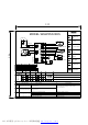

MODEL:WUW35X24DS
T3
21
X3
21
X1
2
1
2
4
1 3
5
X2
1 2
X8
1 23
Display PCB
Main PCB
Condenser
fan
F1 Fan
T1 Inner senor
T3 Defrost
sensor
Mechanical
switch
LED light
Compressor
Transformer
Condenser fan
F1 Fan
T1 Inner senor
T3 Defrost sensor
LED light
Mechanical switch
12V / DC
12V / DC
12V / DC
5V / DC
5V / DC
5V / DC
RD
RD
BK
BK
BK
BK
BK
BK
BK
BK
182
3
X4
2
1
RD
BK
3
186
Main Control
From
Color
To
Color
Voltage
Conditions
Evaporator fan
Compressor
Compressor / condenser fan
Compressor
Run WindingsStart Windings
7.4 6.1
Temperature Resistance (Ω)
T1 Inner senor
T3 Defrost sensor
2400
2400
Code
E1
HI
LO
Faulty description
Inner sensor short circuit.
Inner temperature too high
Inner temperature too low
Faulty checking
Check the wiring and connection between PCB and sensor,
if it open circuit.
a.Check if any refrigerant leakage.
b.Check if the capillary jam
c.Check if the inner fan run normally
Check if the PCB normal.
Faulty repairing
If the connection and wiring is normal, replace
the sensor please.
Repair the leakage and refill.
Clean or replace the capillary.
Repair the wiring or replace the fan
Replace the PCB.
Check the wiring and connection between PCB and sensor,
if it open circuit.
E2
Inner sensor open circuit.
70℉
70℉
Compressor
115V / AC
BK
RD
Transformer
L
N
115V / AC
GND
14.5V / AC
WH
WH
2
CN 11
1
3
4
2
CN 8
1
3
4
2 41 3 5
PDF 文件使用 "pdfFactory Pro" 试用版本创建 www.fineprint.com.cn