30" (76.2 CM) RANGE HOOD Installation Instructions and Use & Care Guide For questions about features, operation/performance, parts, accessories or service, call: 1-800-253-1301 or visit our website at www.whirlpool.com In Canada, call 1-800-807-6777 or visit our website at www.whirlpool.ca HOTTE D’ASPIRATION DE 30" (76,2 CM) Instructions d’installation et Guide d’utilisation et d’entretien Au Canada, pour assistance, installation ou service, composer le 1-800-807-6777 ou visiter notre site Web à www.
IMPORTANT SAFETY INSTRUCTIONS WARNING: TO REDUCE THE RISK OF FIRE, ELECTRIC SHOCK, OR INJURY TO PERSONS, OBSERVE THE FOLLOWING: Use this unit only in the manner intended by the manufacturer. If you have questions, contact the manufacturer. Before servicing or cleaning the unit, switch power off at service panel and lock the service disconnecting means to prevent power from being switched on accidentally.
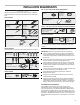
INSTALLATION REQUIREMENTS For 7" (17.8 cm) round vented installations Tools and Parts Gather the required tools and parts before starting installation. Read and follow the instructions provided with any tools listed here. Tools needed Metal snips Wire stripper #2 Phillips screwdriver Flat-blade screwdriver Pencil Drill with ¹⁄₈" (3 mm), ¹⁄₂" (13 mm) and 1¹⁄₄" (3 cm) bits 7" (17.8 cm) round damper Part Number W10355451* Vent clamps as required 7" (17.
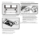
Product Dimensions Venting System 69/16" (16.7 cm) 2" (5.1 cm) Venting Methods 4 15/16" (12.5 cm) 1" (2.5 cm) 7 / 8" (2.2 cm) 9" (22.9 cm) 29 15/16" (76 cm) 1 1/ 2" (3.8 cm) 18 1/2" (47 cm) NOTES: Flexible vent is not recommended. Flexible vent creates both back pressure and air turbulence that greatly reduce performance. The vent system is optional for this model. Vent system can terminate either through the roof or wall. Use 7" (17.8 cm) or larger round vent with a maximum length of 50 ft (15.
For the most efficient and quiet operation: Use no more than three 90° elbows. Electrical Requirements Make sure there is a minimum of 24" (61 cm) of straight vent between the elbows if more than 1 elbow is used. Do not install 2 elbows together. Use clamps or duct tape to seal all joints in the vent system. The vent system must have a damper. If roof or wall cap has a damper, do not use damper supplied with the range hood. Use caulking to seal exterior wall or roof opening around the cap.
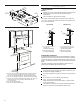
INSTALLATION INSTRUCTIONS NOTES: Depending on your model, determine which venting method to use: roof, wall or non-vented (recirculating). It is recommended that the vent system be installed before the range hood is installed. Go to “Venting System” in the “Installation Requirements” section if you need assistance. Before making cutouts, make sure there is proper clearance within the ceiling or wall for the vent system. 1. Disconnect power Using a #2 Phillips screwdriver, install the drywall anchors.
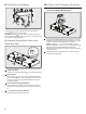
6. Mark Hole Locations 7. Mark and Cut Vent Opening 7" (17.8 cm) Round Vent System 1" (2.5 cm) A Lift the range hood into place and insert the mounting bracket tabs through the slots in the back of the range hood. A Using the 7" (17.8 cm) round vent mounting plate, draw the vent opening outline on the underside of the cabinet: - Place the vent mounting plate on the bottom of the cabinet.
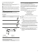
. Drill Electrical Opening 10. Attach Vent Damper or Transition 7" (17.8 cm) Round Vent Mounting Plate A B Using a 1 " (3 cm) drill bit, drill the hole in the dot marked previously at the electrical strain relief. OPTIONAL: Using a " (3 mm) drill bit, drill pilot holes for the dots marked previously at each mounting tab at an approximate 45° angle in an upward direction. 9. Prepare Range Hood Vents and Mounting Tabs x2 F C Using (2) short Phillips head screws, install the 7" (17.
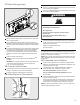
11. Mount Range Hood Option 1 - Direct Wire Installations Use a UL Listed/CSA Approved wire connector and connect the 2 white wires (A) together. Use a UL Listed/CSA Approved wire connector and connect the 2 black wires (B) together. WARNING Fire Hazard Electrically ground the blower. Use copper wire. Connect ground wire to green ground screw in terminal box. Failure to do so can result in death, fire, or electrical shock.
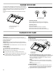
RANGE HOOD USE The range hood is designed to remove smoke, cooking vapors and odors from the cooktop area. For best results, start the hood before cooking and allow it to operate several minutes after the cooking is complete to clear all smoke and odors from the kitchen. The hood controls are located on the front panel of the range hood. Range Hood Controls Off On Off High Low B B A A. On/Off light switch B.
4. Screw a 120V, 9W maximum, LED light bulb with E26 base into the socket. 5. Replace the grease filters. 6. Reconnect power. If the new light does not operate, make sure the light bulb is inserted correctly before calling service. Replacing the LED Light Bulb Turn off the range hood and allow the light bulb to cool. 1. Disconnect power. 2. Remove the grease filters from the hood. 3. Remove the fused light bulb from behind the lamp spacer.
ASSISTANCE OR SERVICE If you need service When calling, please know the purchase date and the complete model and serial number of your appliance. This information will help us to better respond to your request. If you need replacement parts If you need to order replacement parts, we recommend that you use only FSP® replacement parts. FSP® replacement parts will fit right and work right because they are made with the same precision used to build every new Whirlpool® appliance.
SÉCURITÉ DE LA HOTTE DE CUISINIÈRE Votre sécurité et celle des autres est très importante. Nous donnons de nombreux messages de sécurité importants dans ce manuel et sur votre appareil ménager. Assurez-vous de toujours lire tous les messages de sécurité et de vous y conformer. Voici le symbole d’alerte de sécurité. Ce symbole d’alerte de sécurité vous signale les dangers potentiels de décès et de blessures graves à vous et à d’autres.
IMPORTANTES INSTRUCTIONS DE SÉCURITÉ AVERTISSEMENT : POUR RÉDUIRE LE RISQUE D'INCENDIE, CHOC ÉLECTRIQUE OU DOMMAGES CORPORELS, RESPECTER LES INSTRUCTIONS SUIVANTES : Utiliser cet appareil uniquement dans les applications envisagées par le fabricant. Pour toute question, contacter le fabricant.
EXIGENCES D’INSTALLATION Outillage et pièces Rassembler les outils et pièces nécessaires avant d’entreprendre l’installation. Lire et observer les instructions fournies avec chacun des outils de la liste ci-dessous.
Dimensions du produit 2" (5.1 cm) Exigences d’emplacement 69/16" (16.7 cm) Méthodes d’évacuation 4 15/16" (12.5 cm) 1" (2.5 cm) 7 / 8" (2.2 cm) 9" (22.9 cm) 29 15/16" (76 cm) 1 1/ 2" (3.8 cm) 18 1/2" (47 cm) Distances de dégagement à respecter REMARQUES : L'emploi d’un conduit flexible est déconseillé. Un conduit flexible peut causer une rétro-pression et des turbulences de l’air, ce qui réduit considérablement la performance. Le circuit d'évacuation est facultatif pour ce modèle.
Pour un fonctionnement efficace et silencieux : Ne pas utiliser plus de trois coudes à 90°. Veiller à ce qu’il y ait une section droite de conduit d'un minimum de 24" (61 cm) entre les coudes si l'on doit utiliser plus d'un coude. Ne pas installer 2 coudes successifs. Utiliser des brides ou du ruban adhésif pour conduit pour assurer l’étanchéité de chaque jointure du circuit d’évacuation. Le circuit d’évacuation doit comporter un clapet anti-reflux.
INSTRUCTIONS D’INSTALLATION REMARQUES : Selon le modèle, déterminer la méthode d’évacuation à utiliser : évacuation à travers le mur ou le toit, ou recyclage. Il est recommandé que l'installation du circuit d'évacuation soit réalisée avant celle de la hotte. Voir “Circuit d'évacuation” dans la section “Exigences d'installation” en cas de besoin. Avant d’exécuter les découpages, vérifier qu'il existe un dégagement suffisant dans le plafond ou le mur pour le conduit d’évacuation. 1.
6. Marquage de l'emplacement des trous 7. Marquage et découpage de l'ouverture d'évacuation Système d'évacuation circulaire de 7" (17,8 cm) 1" (2.5 cm) A Soulever la hotte et la mettre en place, et insérer les pattes des brides de montage dans les fentes situées à l'arrière de la hotte.
8. Perçage des ouvertures des câbles électriques 10.Fixation du clapet anti-reflux ou du raccord de transition Plaque de montage de conduit circulaire de 7" (17,8 cm) A B C À l’aide d'un foret de 11/4" (3 cm), percer le trou à l'emplacement du serre-câble marqué précédemment. FACULTATIF : À l’aide d'un foret de 1/8" (3 mm), percer des avanttrous aux emplacements de chaque patte de montage marqués précédemment, à un angle d'environ 45° vers le haut. 9.
11. Montage de la hotte Option 1 - Installations avec raccordement par câblage direct Connecter ensemble les 2 conducteurs blancs (A) à l'aide d'un connecteur de fils homologué UL/CSA. Connecter ensemble les 2 conducteurs noirs (B) à l'aide d'un connecteur de fils homologué UL/CSA. AVERTISSEMENT Risque d'incendie Relier le ventilateur à la terre. Utiliser du fil en cuivre. Soulever la hotte et la mettre en place en positionnant les encoches arrières sur les brides de montage.
UTILISATION DE LA HOTTE La hotte de cuisinière est conçue pour extraire fumée, vapeurs de cuisson et odeurs de la zone de la table de cuisson. Pour obtenir les meilleurs résultats, mettre le ventilateur de la hotte en marche avant d’entreprendre une cuisson, et laisser le ventilateur fonctionner pendant plusieurs minutes après l’achèvement d’une cuisson pour pouvoir évacuer de la cuisine toute trace d’odeur de cuisson, vapeur ou fumée. Les commandes de la hotte sont situées sur le panneau avant de la hotte.
4. Installer une ampoule DEL de 9 watts maximum, 120 V, à culot E26. 5. Réinstaller le cabochon : Exercer une pression sur le cabochon pour pouvoir insérer les pattes dans les ouvertures d’insertion. 6. Reconnecter la source de courant électrique. Si la nouvelle lampe ne fonctionne pas, vérifier que l'ampoule est correctement insérée dans sa douille avant de demander l’intervention d’un dépanneur. Remplacement de l'ampoule DEL Éteindre la hotte et laisser l'ampoule refroidir. 1. Débranchez le courant. 2.
ASSISTANCE OU SERVICE Si vous avez besoin de service Lorsque vous appelez, veuillez connaître la date d'achat et le modèle et numéro de série de votre appareil. Ces informations aidez-nous à mieux répondre à votre demande. Caractéristiques et spécifications sur toute notre gamme d’appareils électroménagers. Références aux concessionnaires Whirlpool locaux. Consignes d’utilisation et d’entretien. Vente d’accessoires et de pièces de rechange.