24" (61 CM) RANGE HOOD Installation Instructions and Use & Care Guide For questions about features, operation/performance, parts, accessories or service, call: 1-800-253-1301 or visit our website at www.whirlpool.com In Canada, call 1-800-807-6777 or visit our website at www.whirlpool.ca HOTTE D’ASPIRATION DE 24" (61 CM) Instructions d’installation et Guide d’utilisation et d’entretien Au Canada, pour assistance, installation ou service, composer le 1-800-807-6777 ou visiter notre site Web à www.
TABLE OF CONTENTS TABLE DES MATIÈRES RANGE HOOD SAFETY..................................................................3 INSTALLATION REQUIREMENTS..................................................5 Tools and Parts..............................................................................5 Location Requirements.................................................................5 Venting Requirements...................................................................6 Electrical Requirements................
RANGE HOOD SAFETY Your safety and the safety of others are very important. We have provided many important safety messages in this manual and on your appliance. Always read and obey all safety messages. This is the safety alert symbol. This symbol alerts you to potential hazards that can kill or hurt you and others. All safety messages will follow the safety alert symbol and either the word “DANGER” or “WARNING.
IMPORTANT SAFETY INSTRUCTIONS READ AND SAVE THESE INSTRUCTIONS 4
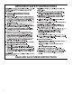
INSTALLATION REQUIREMENTS Tools and Parts Gather the required tools and parts before starting installation. Read and follow the instructions provided with any tools listed here. Location Requirements IMPORTANT: Observe all governing codes and ordinances. ■■ It is the installer’s responsibility to comply with installation clearances specified on the model/serial/rating plate. The model/serial/rating plate is located inside the range hood on the left wall.
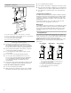
Installation Clearances C ■■ Do not install 2 elbows together. ■■ Use clamps or duct tape to seal all joints in the vent system. ■■ The vent system must have a damper. If roof or wall cap has a damper, do not use damper supplied with the range hood. ■■ Use caulking to seal exterior wall or roof opening around the cap.
3¹⁄4" x 10" (8.3 cm x 25.4 cm) Vent System Calculating Vent System Length To calculate the length of the system you need, add the equivalent feet (meters) for each vent piece used in the system. 7" (17.8 cm) Round Vent System Vent Piece Round 45° elbow 2.5 ft (0.8 m) 90° elbow 5.0 ft (1.5 m) 7" (17.8 cm) wall cap 0.0 ft (0.0 m) Vent Piece 3¹⁄4" x 10" (8.3 cm x 25.4 cm) 90° elbow 5.0 ft (1.5 m) 3¹⁄4" x 10" (8.3 cm x 25.4 cm) flat elbow 12.0 ft (3.7 m) 3¹⁄4" x 10" (8.3 cm x 25.4 cm) wall cap 0.
■■ A 120-volt, 60 Hz., AC-only, 15-amp, fused electrical circuit is required. If the house has aluminum wiring, follow the procedure below: 1. Connect a section of solid copper wire to the pigtail leads. 2. Connect the aluminum wiring to the added section of copper wire using special connectors and/or tools designed and UL Listed for joining copper to aluminum. Follow the electrical connector manufacturer’s recommended procedure.
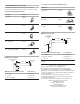
Style 1 - Cut Openings for 3¼" x 10" (8.3 cm x 25.4 cm) Rectangular Vent System Roof Venting To make a 4¹⁄4" x 10½" (10.8 cm x 26.7 cm) rectangular cutout on the underside of cabinet top and bottom: 1. Mark lines ¹⁄2" (1.3 cm) and 4³⁄4" (12.1 cm) from the back wall on the centerline of the underside of cabinet. 2. Mark lines 5¼" (13.3 cm) to the right and left of the centerline on the underside of cabinet. 3. Use saber or keyhole saw to cut a rectangular opening for vent. 4.
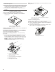
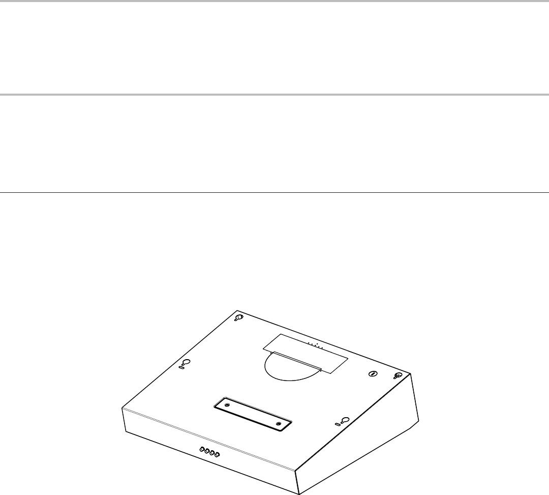
NOTE: The round vent damper may only be installed on the top of the product. Install Vent System 1. Install vent through the vent opening in upper cabinet or wall. Complete venting system according to the selected venting method. See the “Venting Requirements” section. 2. Use caulking to seal exterior wall or roof opening around the cap. Prepare Range Hood B A Only for venting through the top/wall options: 1. Remove vent knockouts, depending on your installation requirements. B A. 3¼" x 10" (8.3 x 25.
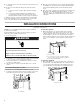
3. Slide the venting lever down as shown in the following image. 6. Bend spring clips away from metal grease filter. 7. Place charcoal filter into top side of metal filter. A A. Lever on No Vented option 4. Replace the venting method screw on the No Vented (recirculating) option. 8. Bend spring clips back into place to secure the charcoal filter to the metal filter. A 9. Replace metal grease filter. A. No Vented method screw 5. Remove the non-vented (recirculating) vent cover. A A.
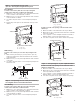
Install Range Hood 1. Remove the power supply knockout from the top or rear of the vent hood (depending on the incoming location of your home power supply cable) and install a UL Listed or CSA Approved ¹⁄2" strain relief. 4. With the aid of a 4.5 x 13 mm screw, mount 2 brackets on the inside front or side face of the cabinet, flush with the cabinet bottom. A 5. Lift the range hood into place, positioning the rear slots over the mounting brackets. A. Power supply knockout 2.
Connect Vent System Make Electrical Connection Connect the ventwork to the range hood. Seal joints with vent clamps or duct tape to make secure and airtight. Check that the backdraft dampers work properly. Option 1 - Direct Wire Installations WARNING Power Supply Cable Installation 1. For direct wire installations, run the home power supply cable according to the National Electric Code or CSA standards and local codes and ordinances.
Option 2 - Power Cord Kit Installations Range Hood Controls For optional power cord kit installations, follow the instructions supplied with the power cord kit. See the “Accessories” section for information on ordering. NOTE: Use only with range hood cord connection kits that have been investigated and found acceptable for use with this model range hood. Complete Installation 1. Replace grease filter if removed. See the “Range Hood Care” section. 2. Check the operation of the range hood fan and light.
RANGE HOOD CARE Cleaning IMPORTANT: Clean the hood and grease filters frequently according to the following instructions. Replace grease filter before operating hood. Exterior Surfaces IMPORTANT: Do not use soap-filled scouring pads, abrasive cleaners, cooktop polishing creme, steel wool, gritty washcloths, or paper towels. To avoid damage to the stainless steel, do not use cleaners that contain chlorine. Cleaning Method: ■■ Rub in direction of grain to avoid scratching or damaging the surface.
WIRING DIAGRAM LED BU BK BK RD BK LED YL WH RD GN Mechanical Push Buttons (4 button 3 Speeds) PUSH BUTTON SWITCH OPERATION L SEL0120629 16 YL/GN GND POSITION OFF NO CONNECTION LAMPS BLACK / YELLOW (L-1) LOW SPEED BLACK / WHITE (L-2) MED SPEED BLACK / RED (L-3) HIGH SPEED BLACK / GREY (L-4) MOTOR SPECIFICATIONS LED DRIVER N BK BU BR RD WH YL M WH YL/GN GN 10uF INPUT: 120 VAC + - BU OUTPUT:700mA (2-15 VDC) BK YL YL BK WH BU FUNCTION POWER SUPPLY 120 VAC FR
ASSISTANCE OR SERVICE If you need service In Canada Please refer to the warranty page in this manual. If you need replacement parts If you need to order replacement parts, we recommend that you use only factory specified parts. Factory specified parts will fit right and work right because they are made with the same precision used to build every new appliance.
WHIRLPOOL® MAJOR APPLIANCE LIMITED WARRANTY ATTACH YOUR RECEIPT HERE. PROOF OF PURCHASE IS REQUIRED TO OBTAIN WARRANTY SERVICE. Please have the following information available when you call the Customer eXperience Center: ■■ Name, address and telephone number ■■ Model number and serial number ■■ A clear, detailed description of the problem ■■ Proof of purchase including dealer or retailer name and address IF YOU NEED SERVICE: 1.
SÉCURITÉ DE LA HOTTE Votre sécurité et celle des autres est très importante. Nous donnons de nombreux messages de sécurité importants dans ce manuel et sur votre appareil ménager. Assurez-vous de toujours lire tous les messages de sécurité et de vous y conformer. Voici le symbole d’alerte de sécurité. Ce symbole d’alerte de sécurité vous signale les dangers potentiels de décès et de blessures graves à vous et à d’autres.
IMPORTANTES INSTRUCTIONS DE SÉCURITÉ AVERTISSEMENT : POUR RÉDUIRE LE RISQUE D'INCENDIE, CHOC ÉLECTRIQUE OU DOMMAGES CORPORELS, RESPECTER LES INSTRUCTIONS SUIVANTES : ■ Utiliser cet appareil uniquement dans les applications envisagées par le fabricant. Pour toute question, contacter le fabricant.
EXIGENCES D’INSTALLATION Outils et pièces Rassembler les outils et pièces nécessaires avant d’entreprendre l’installation. Lire et observer les instructions fournies avec chacun des outils de la liste ci-dessous.
Distances de dégagement à respecter C B D A E ■■ Ne pas installer 2 coudes ensemble. ■■ Utiliser des brides et du ruban à conduit afin d’assurer l’étanchéité de chaque jointure du circuit d’évacuation. ■■ Le circuit d’évacuation doit comporter un clapet anti-reflux. Si la bouche d’évacuation murale ou par le toit comporte un clapet anti-reflux, ne pas utiliser le clapet fourni avec la hotte.
Calcul de la longueur du circuit d’évacuation Pour calculer la longueur effective du circuit d’évacuation nécessaire, additionner les longueurs équivalentes (en pieds ou mètres) de tous les composants utilisés dans le circuit.
L’appareil doit être alimenté que par un circuit de 120 V CA, 60 Hz, protégé par fusible 15 A et mis à la terre. ■■ Si le domicile possède un câblage en aluminium, suivre la procédure ci-dessous : 1. Raccorder une portion de câble en cuivre massif aux conducteurs de raccordement. 2. Connecter le câblage en aluminium à la portion ajoutée de câblage en cuivre en utilisant des connecteurs ou des outils spécialement conçus et homologués UL pour raccorder le cuivre à l’aluminium.
Style 1 — Découpages d’ouverture pour un système d’évacuation rectangulaire de 3¼" x 10" (8,3 cm x 25,4 cm) Style 2 — Découpages d’ouverture pour un conduit d’évacuation rectangulaire de 3¼" x 10" (8,3 cm x 25,4 cm) sur raccord de transition rond. Évacuation à travers le toit Évacuation à travers le toit Découpage d’une ouverture rectangulaire de 4¹⁄4" x 10½" (10,8 cm x 26,7 cm) sur la face inférieure du sommet et du bas du placard : 1.
Style 3 — Découpage d’ouvertures pour un conduit d’évacuation rond de 7" (17,8 cm) Découpage d’une ouverture circulaire sur la face inférieure du sommet et du bas du placard : 1. Tracer un axe central sur la face inférieure du sommet du placard. 2. Tracer une ligne de 5" (12,7 cm) en partant du mur arrière sur la face inférieure du sommet et du bas du placard. 3. Utiliser un compas ou un gabarit circulaire pour tracer un cercle avec un diamètre de ¼" (0,64 cm) supérieur à celui du conduit d’évacuation. 4.
Seulement pour les options avec recyclage de l’air Pour ce mode d’évacuation, il est nécessaire d’acheter un ensemble de filtre au charbon. Voir la section “Accessoires » pour commander. 1. Retirer chaque filtre en tirant sur la poignée à ressort puis en tirant le filtre vers le bas. 2. Enlever la vis de méthode d’évacuation de l’option de ventilation d’un tournevis TORX® T10 et garder pour plus tard. 5. Retirer le cache-conduit sans ventilation (recyclage). A A A. Vis de méthode d’évacuation 3.
Installation de la hotte 1. Ôter l’opercule pour le passage de l’alimentation électrique du sommet ou de l’arrière de la hotte de ventilation (selon l’emplacement du point d’entrée du câble d’alimentation du domicile) et installer un serre-câbles de ¹⁄2" homologué UL ou CSA. 4. À l’aide d’une vis de 4,5 x 13 mm, fixer deux supports sur la partie intérieure avant ou sur le côté du cabinet, en affleurement avec le bas du cabinet. A 5.
G Raccordement du conduit d’évacuation Raccorder le circuit d’évacuation à la hotte. Assurer l’étanchéité des jointures avec des brides de conduit ou du ruban adhésif pour conduit. Vérifier que les clapets anti-reflux fonctionnent correctement. Installation du câble d’alimentation A B 1. Pour les installations à raccordement direct, acheminer le câble d’alimentation du domicile selon les prescriptions du Code national de l’électricité ou des normes CSA et des codes et règlements locaux.
Option 2 — Installations avec l’ensemble du cordon d’alimentation Pour les installations avec l’ensemble du cordon d’alimentation facultatif, suivre les instructions fournies avec l’ensemble du cordon d’alimentation. Consulter la section “Accessoires” pour connaître le processus de commande. REMARQUE : Utiliser uniquement avec des nécessaires de raccordement du cordon d’alimentation de la hotte de cuisinière dont l’utilisation a été testée et déclarée adéquate pour ce modèle de hotte de cuisinière.
ENTRETIEN DE LA HOTTE Nettoyage IMPORTANT : Nettoyer fréquemment la hotte et les filtres à graisse en suivant les instructions suivantes. Replacer le filtre à graisse avant d’utiliser à nouveau la hotte. Surfaces extérieures IMPORTANT : Ne pas utiliser de tampons à récurer savonneux, de nettoyants abrasifs, de crème à polir pour table de cuisson, de tampons en laine d’acier, de chiffons de lavage rudes ou d’essuie-tout.
SCHÉMA DE CÂBLAGE Voyant DEL BU N N R N Voyant DEL JA BL R VE Boutons-poussoirs mécaniques (4 boutons, 3 vitesses) BOUTON-POUSSOIR COMMUTATEUR POUSSOIR ARRÊT JA N BU FONCTION PILOTE DEL BU MAR JA R BL VE ENTRÉE : 120 V CA - SORTIE : 700mA (2-15 V CC) + N BL BU 10uF PAS DE CONNEXION NOIR/JAUNE (L-1) VITESSE BASSE NOIR/BLANC (L-2) VITESSE MOYENNE NOIR/ROUGE (L-3) VITESSE ÉLEVÉE NOIR/GRIS (L-4) LAMPES JA POSTE CARACTÉRISTIQUES DU MOTEUR ALIMENTATION ÉLECTRIQUE FRÉQUENCE A
Si vous avez besoin de service ASSISTANCE OU SERVICE Consultez la page de garantie du présent manuel. Au Canada Si vous avez besoin de pièces de rechange Téléphoner sans frais au Centre pour l’eXpérience de la clientèle canadienne de Whirlpool au : 1-800-807-6777 ou visitez notre site Web www.whirlpool.ca. Si vous avez besoin de commander des pièces de rechange, nous vous recommandons d’utiliser seulement des pièces spécifiées par l’usine.
GARANTIE LIMITÉE DES GROS APPAREILS MÉNAGERS WHIRLPOOL® ATTACHEZ ICI VOTRE REÇU DE VENTE. UNE PREUVE D’ACHAT EST OBLIGATOIRE POUR OBTENIR L’APPLICATION DE LA GARANTIE.
CLAUSE D’EXONÉRATION DE RESPONSABILITÉ AU TITRE DES GARANTIES IMPLICITES LES GARANTIES IMPLICITES, Y COMPRIS LES GARANTIES APPLICABLES DE QUALITÉ MARCHANDE OU D’APTITUDE À UN USAGE PARTICULIER, SONT LIMITÉES À UN AN OU À LA PLUS COURTE PÉRIODE AUTORISÉE PAR LA LOI. Certains États et provinces ne permettent pas de limitation sur la durée des garanties implicites de qualité marchande ou d’aptitude à un usage particulier, de sorte que la limitation ci-dessus peut ne pas être applicable dans votre cas.
/™ ©2016 Whirlpool. Used under license in Canada. All rights reserved. Utilisé sous licence au Canada. Tous droits réservés.