
Installation Instructions


8
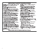
■ A 120-volt, 60 Hz., AC-only, 15-amp, fused electrical circuit
is required.
■ If the house has aluminum wiring, follow the procedure
below:
1. Connect a section of solid copper wire to the pigtail
leads.
2. Connect the aluminum wiring to the added section
of copper wire using special connectors and/or tools
designed and UL Listed for joining copper to aluminum.
Follow the electrical connector manufacturer’s recommended
procedure. Aluminum/copper connection must conform with
local codes and industry accepted wiring practices.
■ Wire sizes and connections must conform with the rating of
the appliance as specified on the model/serial/rating plate.
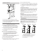
The model/serial/rating plate is located inside the range hood
on the left wall.
■ Wire sizes must conform to the requirements of the National
Electrical Code, ANSI/NFPA 70 (latest edition), or CSA
Standards C22. 1-94, Canadian Electrical Code, Part 1 and
C22.2 No. 0-M91 (latest edition) and all local codes and
ordinances.
INSTALLATION INSTRUCTIONS
Prepare Location
NOTE: It is recommended that the vent system be installed
before hood is installed.
Before making cutouts, make sure there is proper clearance
within the ceiling or wall for exhaust vent.
1. Disconnect "wer.
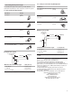
2. Depending on your model, determine which venting method
to use: roof, wall, or non-vented (recirculating).
3. Select a flat surface for assembling the range hood. Place
covering over that surface.
4. Lift the range hood and set it upside down onto covered
surface.
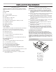
Determine Wiring Hole Location
Cut only one 1¹⁄
4
" (3.2 cm) diameter wiring access hole.
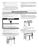
1. Determine and clearly mark a vertical centerline on the wall
and cabinet in the area the vent opening will be made.
A. Centerline
To wire through top:
1. Mark a line distance “A” from the right of the centerline
on the underside of the cabinet. For 12" (30.5 cm) deep
cabinets, mark the "int on this line that is 2" (5.1 cm) from the
back wall. For 15" (38.1 cm) deep cabinets, mark the point
on this line that is 5" (12.7 cm) from the back wall. Drill a 1¼"
(3.2 cm) diameter hole through the cabinet at this "int.
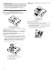
To wire through wall:
1. Mark a line distance “A” from the right of the centerline on
the underside of the wall. Mark the point on this line that is
7
⁄
8
" (2.2 cm) from the underside of the cabinet. Drill a 1¹⁄
4
"
(3.2 cm) diameter hole through the rear wall at this "int.
A. 8³⁄
8
" (21.3 cm)
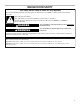
WARNING
Electrical Shock Hazard
Disconnect power before servicing.
Replace all parts and panels before operating.
Failure to do so can result in death or electrical shock.
A
A
Centerline
⁷⁄₈" (2.2 cm
)
Centerline
A
B
A. 8³⁄
8
" (21.3 cm)
B. 2" (5.1 cm) for 12" (30.5 cm) deep cabinets*
5" (12.7 cm) for 15" (38.1 cm) deep cabinets*
*From wall, not cabinet frame