30" AND 36" (76.2 AND 91.4 CM) WALL‑MOUNT CANOPY RANGE HOOD Installation Instructions and Use & Care Guide For questions about features, operation/performance, parts, accessories or service, call: 1-800-253-1301 or visit our website at www.whirlpool.com In Canada, call 1-800-807-6777 or visit our website at www.whirlpool.
TABLE OF CONTENTS TABLE OF CONTENTS....................................................................2 TABLE DES MATIÈRES...................................................................2 RANGE HOOD SAFETY..................................................................2 INSTALLATION REQUIREMENTS..................................................4 Tools and Parts..............................................................................4 Location Requirements.........................................
IMPORTANT SAFETY INSTRUCTIONS READ AND SAVE THESE INSTRUCTIONS 3
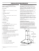
INSTALLATION REQUIREMENTS Tools and Parts Location Requirements ■ Level ■ Drill with 11/4" (3 cm), 3/8" (9.5 mm), and 3/16" (4.8 mm) drill bits ■ Pencil ■ Wire stripper or utility knife ■ Tape measure or ruler ■ Pliers ■ Caulking gun and weatherproof caulking compound ■ Vent clamps ■ Jigsaw or keyhole saw ■ Flat-blade screwdriver ■ Metal snips ■ Phillips screwdriver IMPORTANT: Observe all governing codes and ordinances. Have a qualified technician install the range hood.
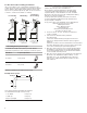
Cabinet Dimensions Venting Requirements (vented models only) 133/8" (34 cm) 15" (38.1 cm) 1413/16" (37.7 cm) Side cabinet Side cabinet 30" (76 cm) or 36" (91.2 cm) “X” bottom of canopy to cooking surface Centerline Cooking surface IMPORTANT: Minimum distance “X”: 24" (61 cm) from electric cooking surface Minimum distance “X”: 27" (68.6 cm) from gas cooking surface Suggested maximum distance “X”: 36" (91.4 cm) The chimneys can be adjusted for different ceiling heights. See the following chart.
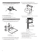
For Non-Vented (Recirculating) Installations If it is not possible to vent cooking fumes and vapors to the outside, the hood can be used in the non-vented (recirculating) version, fitting a charcoal filter and the deflector. Fumes and vapors are recycled through the top grille. See the “Assistance or Service” section for information on ordering. Roof Venting Non-Vented (Recirculating) Wall Venting A A B B B A A. Roof cap B. 6" (15.2 cm) round vent A. Wall cap B. 6" (15.
INSTALLATION INSTRUCTIONS Prepare Location ■ It is recommended that the vent system be installed before hood is installed. ■ Before making cutouts, make sure there is proper clearance within the ceiling or wall for exhaust vent. Check your ceiling height and the hood height maximum before you select your hood. 1. Disconnect power. 2. Determine which venting method to use: roof, wall, or non-vented. 3. Select a flat surface for assembling the range hood. Place covering over that surface. ■ 5.
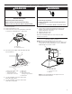
Connect Vent System 1. Install transition on top of hood (if removed for shipping) with (2) 3.5 x 9.5 mm sheet metal screws. For non-vented (recirculating) installation only: 1. Assemble the air deflector with the duct cover bracket with 2 assembly screws provided with the Recirculation Kit. A B A B B C A. Vent transition B. 3.5 x 9.5 mm screw For vented installations only: 1. Fit vent system over transition piece. 2. Seal connection with clamps. 3. Check that back draft dampers work properly. A.
Make Electrical Connection WARNING WARNING Electrical Shock Hazard Electrical Shock Hazard Disconnect power before servicing. Electrically ground blower. Replace all parts and panels before operating. Connect ground wire to green and yellow ground wire in terminal box. Failure to do so can result in death or electrical shock. 1. Disconnect power. 2. Remove terminal box cover. 3. Remove the knockout in the terminal box and install a UL listed or CSA approved 1/2" strain relief.
Metal Grease Filter Complete Installation 1. For non-vented (recirculating) installations only, install charcoal filters over the grease filters, using the clips provided in the kit. See the “Range Hood Care” section. 2. Install metal filters. See the “Range Hood Care” section. 3. Check the operation of the range hood blower and light. See the “Range Hood Use” section. NOTE: To get the most efficient use from your new range hood, read the “Range Hood Use” section.
WIRING DIAGRAM L REMOTE SWITCH Mechanical Push Buttons (4 button 3 Speeds) YL - GN WH FOR ADA COMPLIANCE ADD THESE ELEMENTS DURING THE INSTALLATION. POSITION OFF NO CONNECTION LAMPS BROWN / YELLOW (L-1) LOW SPEED BROWN / WHITE (L-2) MED SPEED BROWN / BLUE (L-3) HIGH SPEED BROWN / BLACK (L-4) YL BR WH BU BR BK PUSH BUTTON SWITCH OPERATION FUNCTION BK L 12.5uF 17.7 BLUE / GREY 27.1 BLUE / RED 34.
ASSISTANCE OR SERVICE In Canada If you need service Please refer to the warranty page in this manual. If you need replacement parts If you need to order replacement parts, we recommend that you use only factory specified parts. Factory specified parts will fit right and work right because they are made with the same precision used to build every new appliance.
SÉCURITÉ DE LA HOTTE DE CUISINIÈRE Votre sécurité et celle des autres est très importante. Nous donnons de nombreux messages de sécurité importants dans ce manuel et sur votre appareil ménager. Assurez-vous de toujours lire tous les messages de sécurité et de vous y conformer. Voici le symbole d’alerte de sécurité. Ce symbole d’alerte de sécurité vous signale les dangers potentiels de décès et de blessures graves à vous et à d’autres.
IMPORTANTES INSTRUCTIONS DE SÉCURITÉ AVERTISSEMENT : POUR RÉDUIRE LE RISQUE D'INCENDIE, CHOC ÉLECTRIQUE OU DOMMAGES CORPORELS, RESPECTER LES INSTRUCTIONS SUIVANTES : ■ Utiliser cet appareil uniquement dans les applications envisagées par le fabricant. Pour toute question, contacter le fabricant.
EXIGENCES D’INSTALLATION Outils et pièces Exigences d’emplacement Rassembler les outils et pièces nécessaires avant d’entreprendre l’installation. Lire et observer les instructions fournies avec chacun des outils de la liste ci-dessous. IMPORTANT : Observer les dispositions de tous les codes et règlements en vigueur. Confier l'installation de la hotte à un technicien qualifié.
Dimensions du placard Exigences concernant l’évacuation (seulement pour un modèle avec décharge à l'extérieur) ■ Le circuit d'évacuation doit décharger l'air à l'extérieur, excepté pour une installation sans décharge à l'extérieur (recyclage). ■ Ne pas terminer le circuit d'évacuation dans un grenier ou dans un autre espace fermé. 1413/16" (37.7 cm) ■ Side cabinet Ne pas utiliser une bouche de décharge murale de 4" (10,2 cm) normalement utilisée pour un équipement de buanderie.
Exemple de circuit d'évacuation Méthodes d’évacuation Cette hotte a été configurée à l'usine pour la décharge de l'air aspiré à travers le toit ou à travers un mur. Un circuit d'évacuation en conduit rond de 6" (15,2 cm) (non fourni) est nécessaire pour l'installation. La hotte comporte une ouverture de sortie de diamètre 6" (15,2 cm). REMARQUE : On déconseille l'emploi de conduit flexible.
INSTRUCTIONS D’INSTALLATION Préparation de l’emplacement ■ Il est recommandé d’installer le circuit d’évacuation avant de procéder à l’installation de la hotte. ■ Avant d’exécuter les découpages, vérifier la disponibilité d’un dégagement suffisant dans le plafond ou le mur pour le conduit d’évacuation. Avant de sélectionner la hotte à installer, mesurer la hauteur libre sous plafond et la hauteur maximum disponible sous la hotte. 1. Déconnecter la source de courant électrique. 2.
Achever la préparation 1. Déterminer et effectuer tous les découpages nécessaires dans le mur pour le passage du circuit d’évacuation. Installer le circuit d’évacuation avant la hotte. Voir la section “Exigences concernant l’évacuation”. 2. Déterminer la hauteur appropriée pour le cordon d’alimentation du domicile et percer un trou de 11/4" (3,2 cm) à cet endroit. 3.
Raccordement électrique AVERTISSEMENT AVERTISSEMENT Risque de choc électrique Risque de choc électrique Déconnecter la source de courant électrique avant l'entretien. Replacer pièces et panneaux avant de faire la remise en marche. Le non-respect de ces instructions peut causer un décès ou un choc électrique. 1. Déconnecter la source de courant électrique. 2. Retirer le couvercle du boîtier de connexion. 3.
Achever l’installation 1. Pour les installations sans décharge à l’extérieur (recyclage) uniquement, installer les filtres à charbon sur les filtres à graisse à l'aide des attaches fournies avec l'ensemble. Voir la section “Entretien de la hotte”. 2. Installer les filtres métalliques. Voir la section “Entretien de la hotte”. 3. Contrôler le fonctionnement de la hotte et de la lampe du ventilateur. Voir la section “Utilisation de la hotte”.
ENTRETIEN DE LA HOTTE Nettoyage IMPORTANT : Nettoyer fréquemment la hotte et les filtres à graisse en suivant les instructions suivantes. Réinstaller les filtres à graisse avant de faire fonctionner la hotte. Surfaces externes Afin d'éviter d'endommager la surface externe, ne pas utiliser de tampons en laine d'acier ou de tampons à récurer savonneux. Toujours essuyer pour éviter de laisser des marques d'eau. Méthode de nettoyage : ■ Savon détergent liquide et eau, ou produit de nettoyage polyvalent.
SCHÉMA DE CÂBLAGE Ph Neu Terre FONCTION POSITION ARRÊT PAS DE CONNEXION LAMPES MARRON / JAUNE (L-1) VITESSE BASSE MARRON / BLANC (L-2) (L-4) JA 12.
ASSISTANCE OU SERVICE Si vous avez besoin de service Pour plus d’assistance Consulter la page de garantie du présent manuel. Si vous avez besoin de plus d’assistance, vous pouvez soumettre par écrit toute question ou préoccupation à Whirlpool Canada à l’adresse suivante : Whirlpool Brand Home Appliances Customer eXperience Centre Whirlpool Canada 200 - 6750 Century Ave.