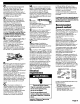
Part No, 8527809 IMPORTANT: Read and save these instructions COMMERCIAL DRYER ELECTRIC IMPORTANT Installer: Leave Installation with the owner. Instructions Owner: Keep Installation Instructions future reference. 120-volt, 60 Hz 120/240-volt, 60 Hz for Save Installation Instructions for local electrical inspector's use. www.whirlpool.
IMPORTANT SAFELYINSTRUC11ONS Before you start... Your safety and the safety of others are very important. We have provided many important safety message in this manual and on your appliance. Always read and obey all safety messages. This symbol is the safety symbol. This alertsalert you to potential hazards that can kill or hurt you and others. All safety messages will follow the safety alert symbol and either the word =DANGER" or "WARNING".
The console houses the electronic control board, The board is factory set for a dry time of 45 minutes, Consult the tech sheet found inside the dryer toe panel to reset dry time and for other options, The coin-slide mechanism, control panel lock and key, and coin-box lock and key are not included and are available from usual industry sources, exhaust airflow beffer [==] good For exhaust systems not covered by the exhaust length chart, see Whirlpool Service Manual, "Exhausting Whirlpool Dryers," Part No,
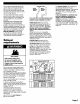
An exhaust hood should cap the exhaust vent to prevent exhausted air from returning into the dryer, The outlet of the hood must be at least 12 inches (30,5 cm) from the ground or anything else that may be in the path of the exhaust, Four-inch outlet hood is preferred.
Cm Check that dryer is equipped with the correct burner for the particular type of gas used, Burner information can be found on the serial/rating plate in the door well of the appliance, If this information does not agree with the type of gas available, see your dealer, D mThis dryer is equipped for use with NATURAL GAS, It is certified by CSA International for manufactured, mixed and L,P, (propane and butane) gases with appropriate conversion, No affempt shall be made to convert the appliance from the gas
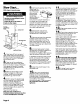
Now Start... With dryer in laundry area. Excessive Weight Hazard Use two or more people to move and install dryer, Failure to do so can result in back or other injury.
Now Start... Electrical requirements Excessive Weight Hazard Usetwo or more peopleto moveand installdryer. Failureto do so can resultin backor other injury. If codes permit and a separate ground wire is used, it is recommended that a qualified electrician determine that the ground path is adequate. With dryer in laundry area... Important: Observe all governing codes and ordinances.
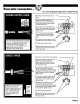
7 • U.S. installations: Make electrical connection, This dryer is manufactured with the cabinet-ground conductor connected to the NEUTRAL(center) of the wiring harness at the terminal block. If local codes do NOT permit this type of connection, use "Fourwire connection" instructions.
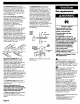
Four-wire connection... Four-wire receptacle (required for mobile homes 4. Remove center terminal block screw. 5. Remove appliance ground wire (green with yellow stripes) from external ground connector screw. Fasten under center, silver-colored terminal block screw. 6. Connect neutral wire (white center) center of power supply screw of the terminal Tighten screw. or block. 7. Connect ground wire (green) of power supply cord to external ground conductor screw. Tighten 8.
Three-wire connection... Three-wire receptacle 4. Loosen or remove center terminal block screw, 5. Connect the neutral wire or center) of power supply cord to the center, silver-colored terminal screw of the terminal block, Tighten screw, 6. Connect the other wires to outer terminal block screws, Tighten screws, 7. Tighten 8. strain Reinstall relief screws, terminal the dryer rear with hold-down block _. cover panel, screw, Secure to _ _ \_ _ cover Where local codes permit connecting ca
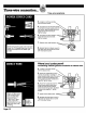
Three-wire connection... Three-wire receptacle Where local codes Do Not permit connecting cabinet-ground conductor to neutral wire: 4. Remove center terminal block screw. 5. Remove the appliance harness ground wire (green with yellow stripes) from the external ground connector screw. Connect appliance the neutral the power the center, block 6. harness ground wire and wire (white or center) of supply cord/cable under silver-colored terminal screw. Connect terminal screws. Tighten screw.
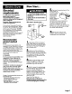
Recessed area and closet installation instructions This dryer may be installed in a recessed area or closet, For recessed area and closet installations, minimum clearances can be found on the serial tag on the dryer, The installation spacing is in inches and is minimum allowable, Additional spacing should be considered for ease of installation, servicing and compliance with local codes and ordinances, If closet door is installed, the minimum unobstructed air openings in top and bottom is required, Louvered
Product dimensions 29" (73.7 cm) dryer _29" _25-I/2" (73.7 cm)_ (64.8 cm) mmmf mmmm I I non-coin-operated models: 7-I/8" (18.1 cm) coin-operated models: 7-718" (20 cm) 35" (88.9 cm) (40.6 cm) 13" 27- I/4" (69.2 cm) 4" (I0.2 cm) _ / dia. I - I/4" (3.2 cm) '-ix._u;T _.>'-_,_.__ =.... r 18-3/8" vi (46.7 cm) I" (2.5 cm) BACK VIEW SIDE VIEW 27" (68.6 cm) dryer _29-I/4" (74.3 cm) _26-1/2" (64.8 cm) ,,'---7 I I non-coinoperated models: 7-I/8" (18.
Piece n° 8527809 IMPORTANT: Lire et conserver ces instructions. IMPORTANT Installateur : Remettre les inslTuctions d'installation au propri6taire. Propd6taire : Conserver les insiTuc-Iions d'install_ion pour consultcrlion ult6rieure. Conserver les inslTuc-Iions d'installcrlion pour consuitallon par rinspecteur local des installations 61eclTiques. www.whirlpool.
Avant de commencer... Votre s_curit_ IMPORTANTES INSTRUCTIONSDESr:CURITI: et celle des autres est tr_s importante. Nous donnons de nombmux messages de sL=curit_importants dans ce manuel et sur votre appareil m_nager. Assurez-vous de toujours lira tous les messages de Voici le symbole secudte et de vous d'alerte y conformer. de secudte. Ce symbole d'alerte de securite vous signale les dangers potenUels de dL=ceset de blessures graves a vous et _ d'autres.
CONSERVEZCESINSTRUCTIONS L'orilice d'6vacuofion de la s6cheuse doit _Te reli6 _ I'ext6fieur. Afficher cet averlJssement en un endroit tr_)svisible.
L'o_il_ du conduit d'6vacualion devrait _lTe dot_e d'une bouche de d_oharge emp_chant I'air _vacu_ de revenir (_ la s_oheuse, L'orifice de la bouche de d_charge dolt _tre situ_ (_ au moins 30,5 cm (12 po) au-dessus du sol ou de taut autre objet silu_ sur la ITajectoire de I'air _vacu_, L'emploi d'une bouche de d6charge de 10,2 cm (4 po) est pr6f6rable.
C m V6rifier que la s_cheuse est @quip_e du br_leur convenable, correspondant au gaz sp_,_cifique qui alimente I'habitation, L'information sur le br_leur se treuve sur la plaque signal6tique, plac_e dans le Iogement de la porte de I'appareil, Si celte information ne correspond pas au Iype de gaz disponible, consulter le marchand, D m La s_,_cheuse est _cluip_e pour I'alimentation au GAZ NATUREL,Elle est homologu_e par CSA International pour I'alimentation avec gaz fabriqu6s, gaz mixtes et gaz liqu@fi@s(prop
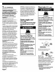
Commencer... Avec Io s_heuse dans Io buanderie. Risque du poids excessif trdliser deux ou plus de personnes pour d_placer et installer la s_cheuse. Le non-respect de cette inst_cnon peut causer une blessure au dos ou d'aube blessure.
Commencer... Spdciflcations de l'installation lectdque Si on uHlise un conducteur distinct de liaison _ la term Iorsque le code local le petrnet, il est recommand6 qu'un 61echicien qualili6 v6dfie la qualit6 de la liaison _ la term. Important : Respecter tous les codes et r_glernents on vigueur.
7 • Installation aux f:.-U. : Ex_cuter le raccordement au circuit _lectrique, Lorede Io fobdcofion de cette s6cheuse, le conducteur de iaison _ la terre connect6 au chassis de la s6cheuse a _ roccord6 ser la borne de connexion du conducteur NEUIRE (cerdrol) du circuit d'alimentalJon. Si le code local ne pen-net pas ce type de roccordement, ex6cuter le roccordement conforrn6ment aux instructions de la section ,, Circuit _ qualTe conducteurs ,,.
Circuit quatre conducteurs... Prise de courant a qualTe conducteurs pour maison mobile) 4. (n6ceuaire Oter la vis de la borne cenlTale du 5. S_parer le conducteur de liaison (_ la terre de I'appareil (vert avec rayure jaune) de la vis de connexion au chassis, Connecter ce conducteur sous la vis cenlTale de teinte argent du bloc de connexion, (blanc ou central) du cordon d'alimentellon sous la vis de la borne cenlTale du bloc de connexion, Serrer la vis, 7.
Circuit trois conducteurs... Prise de courant _ ITOiSconducteurs 4. Desse_er ou enlever la vis de la 5. Connecter le conducteur neutre (blanc ou central) du cordon d'alimentation sur la borne centrale (vis de teinte argent) du bloc de connexion, Serrer la vis, = sur les bornes externes du bloc de connexion, Serrer les vis, 7. Serrer les vis du se_e-c6ble, r_._ 8. R_installer le couvercle du Iogement des connexions sur le panneau arri_re de la s_cheuse, Fixer le couvercle avec la vis, _ _ _ _1 \\\
Circuit trois conducteurs... Prise de courant fi trois conducteurs Si les codes locoux ne permettent pas le raccord.ement entre conducteur de liaison a la terre de la caisse : neutre et conducteur 4. Oter la vis de la borne centrale du bloc, 5.
pout /.
Dimensions du produit Setcheuse 73,7 cm (29 po) _73,7 64,8 cm (25 I12 po) cm (29 po) mmmj t .... I I 12,1 cm (4 3/4 po) m_,m,m _;ABLE _ ............... ELECTRIQUE_ 1 40,6 cm (16 po) 33 cm 10,2 cm I (4po) dia. BOUCHEDE i • Mod61o sans m6canisme de commande a pi6ces : 18,1 cm (7 I18 po) Mod61esavoc m6canismo do commando a pi6cos : 20 cm (7 7/8 po) r ,_ 88,9 cm (35 po) | | 69,2 cm (27 I14 po) 3,2 cm I ......