
Owner's manual

Whirlwind
W1 39 Pin Connector System
Technical Data
Materials and
Finishes:
• Contacts: Copper alloy,
hard gold plate over
nickel under plate per
MIL-G-45204
• Insulators: Low temperature
elastomer
• ‘O’ Rings and Seals;
Low temperature elastomer
• Shells and Dust Caps:
All aluminum alloy, black
anodized coating
Chain-Stainless steel
Mechanical Data:
• Operating Temperature:
-40“C to +105°C
-40°Fto+22rF
• Contacts: #20 AWG Solder
type (7.5 Amp rating)
• Contact Retention:
15 lbs. minimum
• Connector Engagement
and Separation Forces:
32 in. lbs. maximum
• Polarization: 5 Keyways
Electrical Data:
• Operating Voltage; 850
VDC or 600 VAC rmb
maximum
• Insulation Resistance;
5000 megohm minimum
• Contact Resistance;
6 milliohms maximum
The Whirlwind Wl is a 39 contact, quick disconnect connector
system based on the proven MIL-26482 multipin standard. The pin
and socket modules are shell size 20 with a standard 39 contact
insert arrangement. The solder style contacts are permanently
mounted in resilient rubber insulators to provide years of trouble
free service. Whirlwind manufactures a robust aluminum backshell
to protect the soldered connections and provides a waterproof
mesh grip for an absolutely reliable strain relief on the c|ble.
The Wl system utilizes a 39 pin male insert in a plug shell, with
a quarter-turn locking ring and a 39 socket female insert in a
receptacle shell with studs, that mates with the male plug shell.
Whirlwind provides the W1 in four standard configurations, male
and female inline and male and female chassis mount. The Wl can
be used to interconnect up to 12 balanced, shielded signal lines.
W1CF
Female Panel Connector / Cap, Wiring Kit Complete
AB39FP
39 Pin Female Panel Mount Body with Studs
1
AB39CAP
Dust Cap with Ring For Female 39 Pin
1
PT1-16BK-1.5
Drain Wire Insulator 1/16” BIk Shrink Tube 1.5” 13
PT3-16BK-1.0
Mylar / Foil Insulator 3/16” BIk Shrink Tube 1.0”
13
PTM6BK-0.5
Solder Cup Insulator 1/16” BIk Shrink Tube 0.5"
39
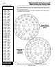
Wl Pin Out
Wiring Diagram For 39 Pin
1
W1CM
Male Panel Connector / Cap, Wiring Kit Complete
AB39MI
39 Pin Male Inline Body with Ring
1
AB39MPA
Panel Mount 39 Pin BIk Flange with Set Screw
1
AB39CAPWT Dust Cap with Studs For Male 39 Pin
1
PT1-16BK-1.5
Drain Wire Insulator 1/16” BIk Shrink Tube 1.5”
13
PT3-16BK-1.0
Mylar / Foil Insulator 3/16” BIk Shrink Tube 1.0”
13
PT1-16BK-0.5
Solder Cup Insulator 1/16” BIk Shrink Tube 0.5”
39
Wl Pin Out
Wiring Diagram For 39 Pin
1
W1IF
Female Inline Connector / Cap, Wiring Kit Complete
AB39FI
39 Pin Female Inline Body with Studs
1
AB39CAP
Dust Cap with Ring For Female 39 Pin
1
AB39H
39 Pin inline Housing with Set Screws
1
AB60G
39-61 Inline Strain Relief Grip Range .375”-.50”
1
ABKR
16mm Split Ring For Dust Cap Chain
1
PT1-16BK-1.1
Drain Wire Insulator 1/16” BIk Shrink Tube 1.1”
13
PT3-16BK-0.5
Mylar / Foil Insulator 3/16” BIk Shrink Tube 0.5”
13
PT1-16BK-0.5
Solder Cup Insulator 1/16” BIk Shrink Tube 0.5”
39
W1 Pin Out
Wiring Diagram For 39 Pin
1
W1IM
Male Inline Connector / Cap, Wiring Kit Complete
AB39MI
39 Pin Male Inline Body with Ring
1
AB39CAPWT
Dust Cap with Studs For Male 39 Pin
1
AB39H
39 Pin Inline Housing with Set Screws
1
AB60G
39-61 Inline Strain Relief Grip Range .375"-.50"
1
ABKR
16mm Split Ring For Dust Cap Chain
1
PT1-16BK-1.1
Drain Wire Insulator 1/16” BIk Shrink Tube 1.1”
13
PT3-16BK-0.5
Mylar / Foil Insulator 3/16” BIk Shrink Tube 0.5”
13
PT1-16BK-0.5
Solder Cup Insulator 1/16” BIk Shrink Tube 0.5”
39
Wl Pin Out
Wiring Diagram For 39 Pin
1
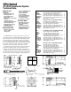
io^
//{/// o *
Hi n ^ o <
If 1 If ^ ^ <
ll 1 1 ° ® ^
O f,
o ^ ^ \ Yt
0 0 \\ \ \\
a o o |] I ]
o ® ® jf^i a
0 o j) j a
39 Pin Chassis Male
Q i Q Dmin wire insulator Solriar cup insulator Foil insulator
3.r
------
(3.53’ (with dust cap In place)
(Strain relief Bushing adds approximately 2’ to rear of oonnector)
1.20’ (with dust cap In place)
39 Pin Chassis Female
1.46’
(Chassis connectors
mount on front of panel)
CaUe
l¥marfltloii
durnm
—■ 0 .147" for 110 screw
0 .172’for *S screw
2.0’
(2.5’ for panel mount)
3.1"
--------
lü»
(3.S3’ with dust cep in place)
39 Pin Chassis Female