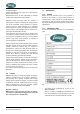
USERS MANUAL M-SQ25 - 1500 RPM - Marine diesel generating set 230/400V / 50Hz Digital Diesel Control Art.nr. . 40200441 WHISPER POWER BV Kelvinlaan 82 9207 JB Drachten Netherlands Tel.: +31-512-571550 Fax.: +31-512-571599 www.whisperpower.eu V1.
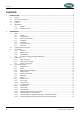
CONTENTS CONTENTS: 1 INTRODUCTION .............................................................................................................................................................. 4 1.1 General .............................................................................................................................................................. 4 1.2 Service and maintenance ..................................................................................................................
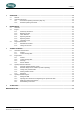
CONTENTS 3 OPERATION .................................................................................................................................................................. 20 3.1 General ............................................................................................................................................................ 20 3.2 Operating Instructions ............................................................................................................................
INTRODUCTION 1 INTRODUCTION 1.1 General This manual applies to the WhisperPower M-SQ25 generating set controlled by Digital Diesel Control first launched in September 2005. For other models see other manuals available on our website: www.whisperpower.eu. The M-SQ25 Marine Diesel Generating set is manufactured and marketed by WhisperPower. It is important to read this manual before installing and operating the generating set.
INTRODUCTION Example 4: Neglect Whisper generators have an option for an auto start/stop mode or interval mode. WhisperPower cannot be held responsible for damage caused by the unattended running generator. Guarantee means that faulty parts are repaired or replaced free of charge. If necessary the whole generator unit will be exchanged.
INTRODUCTION 4 FREQUENCY. This is shown in Hz and is determined by the speed of the engine (RPM). 50 Hz correlates with 1500 rpm. 5 CURRENT. This shows the maximum current that is acceptable at the specified frequency, voltage and power factor. When connected in tri phase the indicated current is the current between two phases that can be taken off three times. 6 WEIGHT shows the net dry weight (approximately) in kg.
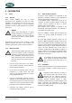
INFORMATION 2 INFORMATION 2.1 Safety 2.1.1 General When correctly installed and used in normal circumstances this generating set fulfils EC safety regulations. This generating set could be part of an installation or could be used in a way that additional regulations of the EC or other authorities have to be taken into account.
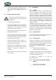
INFORMATION 2.1.5 Operation External moving parts like fans and V-belts are covered by the canopy and therefore the M-SQ25 is very safe when the canopy is closed. BREAK THROUGH HERE Nevertheless take note of the signs on the generating set which show symbols in a triangle indicating danger. When service has to be carried out while the engine is running, be aware of moving parts like V-belts. • The generating set should be operated by authorised personnel only.
INFORMATION produced which cannot be removed from the skin. If signs of decomposition are evident, or if in doubt, always wear disposable heavy duty gloves. 2.2 Transport, lifting and storage When lifting the generating set avoid any risk of personal injuries, do not stand under the generating set. • Use soft slings to avoid damage • On the engine are lifting eyes, which can be used to take the generator out of the capsule.
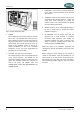
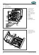
INFORMATION 2.4 2.4.1 Components Main components 01 02 03 04 05 06 07 08 09 10 11 12 13 14 Thermostat housing Boiler connection Engine coolant pump V-belt Exhaust connection Bypass cooling water out Bypass cooling water in Battery + Battery Fuel out Fuel in Raw water inlet Raw water pump Rubber engine mounting 15 16 17 18 Filler cap engine oil Filler cap engine coolant Rubber engine mounting Rocker cover Fig. 4: Left View main components M-SQ25 Fig.
INFORMATION 19 20 21 22 23 24 25 26 27 28 29 30 31 32 33 34 35 36 Hoist eye rear Engine speed adjusting screw Fuel injector Glowplug (4x) Fuel filter Fuses Control panel Air cleaner element Indentification plate Oil swump handpump Coolant drain plug Engine oil dipstick Fuel solenoid Oil filter Injection pump air bleeding screw Fuel lift pump for manual primimg Fuel injection pump Heat exchanger Fig. 6 Front View main components M-SQ25.
INFORMATION 2.4.2 Generator control panel 2.5 2.5.1 Start / Stop Internal fuel pump Digital Diesel Control Fuse 3A Fuse 3A Remove fuse before maintenance Auxiliary Fuse 10A External Fuel Pump Fuse 3A Whisper Digital Diesel Operation Unit Observe instructions in the manual Replace fuses with same type and rating Fig. 8 Control panel. Fig. 9 Digital Diesel Control unit 2.4.
INFORMATION 2.5.2 Engine The M-SQ25 generating set is based on the Mitsubishi S4S 4 cylinder 4 stroke diesel engine. The engine is indirectly injected. The engine is water cooled and the cooling liquid is cooled by a heat exchanger and raw (sea) water. The heat exchanger and all other parts which are in direct contact with the raw (sea) water are made of seawater resistant material like naval brass and copper nickel.
INFORMATION 2.5.7 2.5.8 recommendations. Using the wrong specification will cause high oil consumption. Control The generating set can be operated by push buttons on the panel on the alternator or by the remote control. By pushing the START button the control system is activated and will start the engine automatically. Pushing the STOP button will stop the engine and the electrical system will be deactivated. Stopping the engine is executed by the solenoid that will shut off.
INFORMATION 2.5.
INFORMATION 2.5.15 Electrical diagram control wiring M-SQ25 Fig.
INFORMATION 2.5.16 Terminal modes 115VAC – 230VAC - 400VAC 50H Fig.
INFORMATION 2.5.17 Generator Diagram 3 phase with AVR 230V – 400V 50Hz with AVR * TO CONNECT NEUTRAL TO GROUND REFER TO 2.1.3 USER MANUAL WHISPER 25U * Fig 15.
INFORMATION 2.5.18 AC Wiring Diagram single phase with AVR 230V Hz (Double Delta) * TO CONNECT NEUTRAL TO GROUND REFER TO 2.1.3 USER MANUAL WHISPER 25U Fig 16.
OPERATION 3 OPERATION 3.1 General The generating set is operational after full installation and filling up with: fuel, engine lubricating oil and cooling liquid, filling the starter battery with acid (WhisperPower batteries do not need to be filled up and are sealed), connecting the remote control panel. 1 Max. oil level; 2 Min. oil level. Fig. 17 Engine Oil Dipstick markings. 3.2 Operating Instructions 3.2.
OPERATION 2 3 4 5 6 7 Check sea water cocks. Do not forget the valve of the water outlet in case of a water/exhaust gas separator. Check the water strainer. Check for leakages. Regularly check the siphon vent in the cooling water supply. If no Masterswitch is used: Switch main Power Source Selector switch to "OFF" or switch off all devices. Switch on the battery switch. Starting the generator: By pushing the start button briefly the electric system is activated and the starting procedure will begin.
OPERATION Stopping the generating set: 1 Avoid stopping of the generator abruptly after a long period of operation at high load! Doing so, you avoid unnecessary thermal load to your generating set! Act as follows: Prior to switching off the generating set, decrease the generator load (i.e. turn off most electrical users) and let the generator run at low load for approx. 5 minutes to allow the engine to get properly cool (the influent sea water must flow through the system in order to cool the engine).
MAINTENANCE 4 MAINTENANCE 4.1 Alternator The alternator does not require any maintenance. Periodic inspection and cleaning is recommended, depending on environmental conditions. However when the alternator has been idle for a long period attention to winding condition is recommended. The condition of windings can be assessed by measurement of insulation resistance to earth. (See 5.3.5 Meggering) The alternator bearing is greased for life and is therefore not regreasable 01 4.2 4.2.
MAINTENANCE 4.2.5 Replacing oil filter Replacement has to be executed according to the schedule in this manual. Drain the oil using the sump pump and put some tissues under the filter. 01 02 Fig. 21 Location rubber packing-ring oil filter. A smear of oil has to be put on the seal of the filter before fitting the filter. The filter should be fastened manually: when the rubber touches the metal turn 3/4 further. 4.2.6 01 Engine oil filter 02 Engine oil dipstick Fig.
MAINTENANCE 4.3 Regular maintenance CHECK DAILY: • Oil level Take care the oil level is never below the mark. Do not add oil when the level is still above the mark. EVERY 150 HOURS: • Change oil. • Check the battery acid level (not for WhisperPower batteries). • Check battery terminals for corrosion • Check and readjust V-belt • Check impeller raw water pump (durability depends on the purity of the sea water. In sandy water and warm water wear will increase).
MAINTENANCE 4.3.1 Maintenance schedule 4.3.2 Check oil level daily Check water inlet filter daily Check the level of the cooling liquid daily Check hoses for loose connections or deterioration daily Change oil and oil filter after first 50 hours Check and tighten nuts, bolts, etc.
TROUBLE SHOOTING 5 TROUBLE SHOOTING 5.1 Alternator/ electrical faults CAUTION! Remove 3 Amp. Fuse in the control panel while working on the generator to prevent the engine to start DANGER! Take care for parts which are live! 5.1.1 General If any problem should occur, check basic conditions and examine all external wiring, switch gear and circuit breakers. Also check if measuring instruments give the correct value. If in doubt, measure directly on the alternator terminals with an independent instrument.
TROUBLE SHOOTING PROBLEM CAUSE • Rotor diode broken. SOLUTION Check the diode in the rotor (see special procedures). The M-SQ25 has one diode block/rectifier unit. Generator output voltage too low when no load is on it (less than 225V between phase and neutral). • Engine is not reaching the rated RPM. See special procedures to readjust RPM. • Faulty AVR. When slightly too low, adjustment could be necessary Try to readjust AVR.
TROUBLE SHOOTING When the engine is cranking, well starting problems almost always originate from lack of fuel or air bubbles in the fuel pipes. CAUTION! When the engine does not start instantly, prolonged cranking can fill up the exhaust system with cooling water because of the water injected exhaust. When the water enters the cylinder through the valves this will Failure code COMMUNICATION LOW START BAT ALTERNATOR EXHAUST TEMP WATER TEMP OIL PRESSURE LOW VOLTAGE HIGH CURRENT FREQUENCY 5.2.
TROUBLE SHOOTING PROBLEM CAUSE • Wrong valve clearance. • Low compression because of dirty valves. • Blocked injector. • Loss of compression by wear out or damage • Unsuitable contaminated fuel • Lack of fuel. • Choked fuel filter. Engine runs irregularly. SOLUTION Adjust valve clearance, Clean valves. Take off the injection bent and inspect the outlet port. When little rust in the port clean the valve by taking off the valve spring and rotate until clean.
TROUBLE SHOOTING PROBLEM Engine starts, but stops after 10 seconds CAUSE • Protection system stops the engine; this can be caused by oil pressure failure, lack of cooling water (exhaust temperature alarm). Overload, loose wire or faulty alarm switch. Digital Diesel Control will help to indicate failure. SOLUTION See paragraph 2.5.5. and 3.2.2 for information on the alarm system. Bypassing the switches can help to confirm the failure.
TROUBLE SHOOTING 32 November 2010 / M-SQ25 / EN
TROUBLE SHOOTING 5.2.3 Warnings CAUTION! Generator must be shut off immediately if: ● Motor RPM suddenly rises or drops. ● Unusual noise comes from generating set. ● Exhaust gases suddenly colour dark. ● Engine failure warning light is on. 5.2.4 the bottom speed protection should first be calibrated.
TROUBLE SHOOTING 5.3.2 Residual voltage check / excitation procedure (flashing) rectifier unit. One can get access to the diode unit by taking off the backend of the alternator. When residual magnetism disappears there is no residual voltage. Residual magnetism can disappear after the generating set being out of service for a long period or a short circuit. This can be solved by exciting the exciter field coil directly, disconnecting the AVR first.
TROUBLE SHOOTING 5.3.5 Meggering One can try to measure resistance between the housing and the windings with a multimeter which should read infinity. When readings are infinity but a fault is suspected one can do a high voltage resistance test (MEGGERING) This procedure should be carried out by an expert. The AVR should be disconnected during this test. A 500V ‘Megger’ or similar instrument should be used. The insulation resistance to earth of all windings should be in excess of 2 MOhm.
TROUBLE SHOOTING 5.4.2 Adjusting valve clearance and retightening the cylinder head bolts. Both procedures have to be executed with a cold engine. When both procedures are executed be sure to retighten the cylinder head bolts before adjusting the valve clearance. When retightening the cylinder head bolts, drain the coolant by removing the coolant drain plug (ref. to fig. 4).
TROUBLE SHOOTING 5.4.4 Disassembling instructions It could be necessary for repair or checks to disassemble the generating set. Following instructions will help: 1 The design of the M-SQ25 makes it possible to do most repairs on the spot. The heat exchanger is accessible and can be removed. The connections of the alternator are very accessible as well. 2 The sound shield canopy can be disassembled according to exploded view below. Fig.
TROUBLE SHOOTING 3 4 To take the generating set out of the canopy all hose and cable connections have to be taken off. The set is fixed to its base by four rubber mountings and can be loosened by removing the four nuts from the bolts of these mountings.
SPARE PARTS 6 SPARE PARTS A complete parts manual in English is available as an option number: number: 40200187 (***) A work shop manual in English is available as an option, number: 40200174 (***). We recommend the following spares for service and maintenance.
SPARE PARTS 40 November 2010 / M-SQ25 / EN
SPARE PARTS EN / M-SQ25 / November 2010 41
MAINTENANCE LOG MAINTENANCE LOG first service after 50 hours: hour counter: remarks: next service (every 150 hours): hour counter: remarks: 42 November 2010 / M-SQ25 / EN
NOTES NOTES EN / M-SQ25 / November 2010 43
Kelvinlaan 82, 9207 JB Drachten, Netherlands Tel : + 31-512-571550 / Fax : + 31-512-571599 www.whisperpower.eu / info@whisperpower.