INSTALLATION MANUAL FOR MOBILE APPLICATIONS W-SC6 / SC10 - 3000 RPM - Mobile diesel generating set 230V / 50Hz Digital Diesel Control Art.nr. 40261121 WHISPER POWER BV Kelvinlaan 82 9207 JB Drachten The Netherlands Tel.: +31-512-571550 Fax.: +31-512-571599 www.whisperpower.
TABLE OF CONTENTS TABLE OF CONTENTS: 1 INTRODUCTION .............................................................................................................................................................. 3 1.1 General .............................................................................................................................................................. 3 1.2 Generating sets for vehicles ...........................................................................................
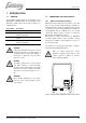
INTRODUCTION 1 INTRODUCTION 1.1 GENERAL This installation manual applies to the installation of the W-SC6/SC10 -3000RPM mobile diesel generating set, first launched in August 2008. This manual is valid for the following models: Part number 41102020 Description W-SC6, 230V 3000rpm Mobile 41102026 W-SC6, 230V 3000rpm Mobile -ungrounded 41104020 W-SC10, 230V 3000rpm Mobile 41104026 W-SC10, 230V 3000rpm Mobile -ungrounded For other models see our website: www.whisperpower.
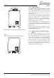
INTRODUCTION 1.2.2 Why two radiators: The optimum engine operating temperature is between 87° and 92° Celsius. The radiator reduces the tempe rature of the cooling liquid by only 5°C to 12°C. The retu rning “cold” coolant therefore has a minimum temperature of approx. 75° Celsius. The alternator should be kept as cool as possible. In practice an alternator starts getting less efficient above 40° Celsius. It is hardly possible to cool down the coolant of the alternator below 40° by using a radiator.
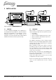
INSTALLATION 2 INSTALLATION Figure 4: Schematic installation diagram 2.1 GENERAL To ensure reliability and durability of the equipment, it is very important that the installation is carried out with the utmost care and attention. To avoid problems, such as temperature problems, noise levels, vibration, etc. the instructions set out in this manual must be followed and all installation work must be carried out professionally. 2.
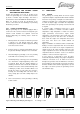
INSTALLATION 2.3 INSTRUCTIONS FOR OPTIMAL SOUND AND VIBRATION INSULATION Position the generating set as low as possible in the vehicle. The generating set is secured to the base frame by means of flexible engine mountings. This frame is mounted in the vehicle with additional vibration dampers. When it is possible to mount the unit directly on the chassis of the vehicle this has advantages in preventing vibrations by resonance. 2.3.
INSTALLATION WHEN NOT USING THE FILTER, THIS HOLE SHOULD BE OPENED 50230003 AIRCLEANER 50230005 ADAPTER 50230006 AIRCLEANER + ADAPTER Figure 6: Mounting of the air strainer element 2.4.2 Air strainer element Applying a generator in a vehicle, where combustion air is taken in from below the vehicle, there is often much dust, sand and dirt in the air. For these applications prescribes the installation of an air strainer element.
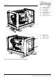
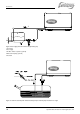
INSTALLATION 01 02 03 04 05 06 07 08 Coolant generator in Battery positive (+) Fuel out Ø8mm Fuel in Ø8mm Battery negative (–) Coolant engine out Coolant engine in Coolant generator out 10 11 12 13 Expansion tank Exhaust 1½” AC power output Remote control Fig.
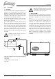
INSTALLATION 2.5.1 Fuel supply 1 FUEL TANK Fuel tanks should be made of appropriate material such as (stainless) steel or plastic. Steel tanks should not be galvanised or painted inside. Condensation can occur in metal tanks when temperature changes. Therefore, water accumulates at the bottom of the tank and provisions should be made for the drainage of this water.
INSTALLATION 1 2 5 A 3 4 Figure 9: Fuel supply (fuel tank is below the generating set) 1 Fuel return 2 Fuel supply 3 Prefilter / Water separator (optional) 4 Extra fuel lift pump (optional) 5 Fuel tank Figure 10: Fuel line assembly with vertical mounted pump and fuel lift pump mounted in an angle 10 September 2008 / W-SC6/10 for mobile applications / EN
INSTALLATION 3 FUEL PIPES When the tank is above the generating set (figure 8) we recommend ending the return line on the top of the tank. When the return is on the top - in case of a leakage the return line cannot overflow because of siphoning. One will only need a fuel cock in the fuel supply line. When the tank is below the generating set we recommend ending the return line on the bottom of the tank (A) below the inlet of the supply line.
INSTALLATION Figure 12: Ventilating an air trap Special attention should be paid to the ventilation of the systems. Each installation system is standard supplied with an expansion tank for the coolant, which is also used to release air bubbles and makes it possible to add coolant into the system in an easy way. This expansion tank should be at the highest point of the system and mounted as high as possible. Most cooling problems originate from air traps blocking the circulation of the engine coolant.
INSTALLATION When mounting the radiators it is important to take care that the outgoing connection, which is the connection to the engine inlet, is on the top position (refer to figure 15 detail A) and is connected to the expansion tank. Also when the radiator is mounted flat at the bottom of the vehicle the outgoing connection is connected to the expansion tank. This is the best way to have the system release air and to add liquid when necessary.
INSTALLATION 2 HOW AND WHERE TO MOUNT THE RADIATORS The radiator kit includes rubber mountings to prevent vibrations to be transferred to the body of the vehicle (figure 17). Due to the difference between vehicles general instructions are not available. One has to find out where the best place for mounting is. For OEM customers Whisper Power can supply a special customised installation kit. Figure 19. Making use of the space below the floor to get an optimal flow of air through the radiators.
INSTALLATION Roof mounted radiators 2.5.3 The radiators on the roof is often the best option from the point of view of keeping the noise of the fans away from people and it will give the best result in dissipating the heat. However, often this option conflicts with the possible need to keep the vehicle as low as possible. An other disadvantage is that the piping has to go through the roof which requires provisions to be waterproof.
INSTALLATION A negative feature of a dry exhaust system is the heat radiated by its components. Measures are taken to overcome the heat problem: The exhaust bent to bring the exhaust out of the canopy is cooled by water. Insulation blankets are included in the exhaust kit to insulate the flexible bellow and the first muffler. When a dry exhaust has its outlet on the roof, all the pipes inside the vehicle has to be insulated.
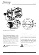
INSTALLATION 2.5.4 Electrical installation (12 Volt) 1 DIGITAL DIESEL CONTROL SYSTEM The electrical control system is standard in 12 Volt with negative earth. Non- earth return is available as an option. All electrical wiring has been prepared on the generating set to the control panel prior to despatch from the factory. The engine is controlled by a very advanced microprocessor based system: Digital Diesel Control. The “black box” containing the microprocessor is located on top of the alternator.
INSTALLATION by an emergency switch or a potential free fire alarm switch with normally closed contacts Remove bypass between J7 - J18 local control panel (rear view) Normal operation Alarm / emergency Fig. 27: Connection for emergency stop / fire alarm switch Automatic starting and stopping Automatic start/stop Whisper Power cannot be held responsible for damage caused by the unattended running generator using the autostart/stop mode or interval mode.
INSTALLATION battery in good condition when the generating set is not used. A battery charger is not included in the standard supply. A high efficiency battery charging unit can be ordered from Whisper Power which is able to charge both the vehicles’s main battery and the starter battery. Also a small charger can be used to charge the starter battery only, such as the IVO SMART 12/10. A battery switch and a charger are included in the battery installation kits, art. no.
INSTALLATION 2.5.5 AC power system (230 Volt) The electric power supplied by the generator is of a high voltage and dangerous to people. Before working (installation) on the system read the sections on safety in the users manual. Realise hat people are not used to have 230V available on a vehicle. Put warning signs on wall sockets and on junction boxes. Instruct non-regular users of the vehicle. Warn maintenance personal of garages that do service on the vehicle.
INSTALLATION SPECIFICATIONS 3 INSTALLATION SPECIFICATIONS 3.1 GENERAL 1 Make a hole for combustion air in the sound shield. Mount an air inlet filter (if required) 2 Mount the generating set directly, without additional vibration dampers, on a solid surface. 3 Mount the cooling system for the engine 4 Mount the cooling system for the alternator 5 Connect exhaust system. 6 Connect ‘fuel supply line’ to the water separator/ fuel filter. 7 Connect ‘fuel return line’ to the fuel tank.
INSTALLATION SPECIFICATIONS 3.3 TECHNICAL DATA W-SC6 AND W-SC10 Model W-SC6 W-SC10 Dimensions (l x w x h) Weight including sound shield 69.0 x 52.5 x 58.0 cm 200 kg (440Lbs) 80.5 x 52.5 x 58.0 cm 240kg (530Lbs) Max. operation angle Remote panel 15 m cable 25° Digital Diesel Control System 25° Battery capacity min. Fuel consumption 12V / 60Ah 1-2.5 litre/hour, load dependent 12V / 60Ah 1-4 litre/hour, load dependent Combustion air consumption Model fuel pump 0.95 m3/min.
INSTALLATION SPECIFICATIONS 3.
INSTALLATION SPECIFICATIONS Included are all fittings to fit copper pipes 8 mm outer diameter or rubber fuel hoses 8 mm inner diameter, or both Figure 29: Installation materials battery and fuel kit 24 September 2008 / W-SC6/10 for mobile applications / EN
INSTALLATION SPECIFICATIONS DRY EXHAUST KIT 1½” no 61 qty 1 article no 50220043 description Exhaust hose SS 500mm fem./male 1½” 62 63 1 1 50220042 50230523 Insul. blanket 35x60 exhaust hose 1½’ Absorbtion muffler steel 1½” 64 65 1 1 50230524 50230525 Ressonance muffler steel 1½” Insul.
INSTALLATION SPECIFICATIONS Figure 30: radiator cooling kit engine, exhaust kit and radiator cooling kit alternator 26 September 2008 / W-SC6/10 for mobile applications / EN
INSTALLATION SPECIFICATIONS RADIATOR COOLING KIT ENGINE 230VAC no 1 qtt 1 article no 50230304 description Radiator cooler AP 300/2 E 230VAC 2 3 2 1 50221502 50221064 Hose clamp stainless19-29 “Male nipple 1” 4 5 1 2 50221044 50221010 “TEE fitting 1” Male hose connection 1x25 6 7 1 1 50221103 50221004 “Straight reducer m/f 1”-3/4” Male hose connection 3/4x20 8 9 1 4 50212409 50201121 Temperature switch 87-82 degr Vibration mounting 30x25 10 11 4 4 50211152 50211465 Bolt hexagonal ZP M
DIAGRAMS & DRAWINGS 4 DIAGRAMS & DRAWINGS LAYOUT GENERATOR CONTROL WITH 230VAC FAN Optional control for two speeds fans. See chapter 4.6 ALTERNATOR TEMP. SWITCH 4.
DIAGRAMS & DRAWINGS LAYOUT GENERATOR CONTROL WITH 12VDC FAN Optional control for two speeds fans. See chapter 4.7 ALTERNATOR TEMP. SWITCH 4.
DIAGRAMS & DRAWINGS LAYOUT GENERATOR CONTROL WITH 24VDC FAN ALTERNATOR TEMP. SWITCH 4.3 Optional control for two speeds fans. See chapter 4.
DIAGRAMS & DRAWINGS 4.
DIAGRAMS & DRAWINGS 4.
DIAGRAMS & DRAWINGS 4.6 ELECTRICAL DIAGRAM RADIATOR FAN CONTROL 230VAC MAIN CIRCUIT BREAKER L1 GENERATOR AC LOAD N CIRCUIT BREAKER AIR FANS 6A Figure 35: Electrical diagram for standard fan control using 230V AC radiator fans BAT. +12V 4 FUSE 5A PUMP +12V 1 GENERATOR 230VAC (L1) 11 FUSE 6.
DIAGRAMS & DRAWINGS 4.7 ELECTRICAL DIAGRAM RADIATOR FAN CONTROL 12 / 24 VDC CONTROL PANEL PUMP 2 4 + BAT. 1 – BAT. 2 FUSE 20/40A 5 1 K3 K3 2 3 7 6 5 K2 3 3 80-70°C 9 45-35°C M M 5 8 3 1 1 K1 K1 K2 4 5 10 2 2 THERMOSTAT COOLER ENGINE GENERATOR RADIATOR COOLER ENGINE GENERATOR JUCTION BOX AIR FANS TERMINAL BLOCK 1 2 3 4 5 6 7 8 9 10 + - - + + - + - K1 K2 FUSE 20/40A CU0,75 CU4 CU2,5 CU0,75 CU0,75 CU2.
DIAGRAMS & DRAWINGS 4.8 WIRING DIAGRAM ELECTRONIC GOVERNOR Figure 38: Electronic governer. In addition to the mechanical governor, the W-SC 6 and 10 are standard equipped with an electronic governor. A governor keeps the speed (RPM=Rotations Per Minute) of the engine at a fixed value. The RPM of the engine correlates with the frequency of the electrical output (3000 RPM =50 Hz) of the alternator. Under full load the RPM of the Whisper models that have only a mechanical governor can drop 75 RPM (=2.
DIAGRAMS & DRAWINGS 4.
DIAGRAMS & DRAWINGS 4.10 DIMENSIONS W-SC6:397 W-SC10:510 W-SC6:530 W-SC10:674 W-SC6:690 W-SC10:804 Figure 40: Outer dimensions (mm) W-SC 6 and 10 CONNECTIONS • exhaust: • fuel hose: • radiator alternator: • radiator engine: • battery +: • battery -: W-SC6 1 ½” 5/16” (8 mm) 3/4” (19 mm) 1” (25.
NOTES NOTES 38 September 2008 / W-SC6/10 for mobile applications / EN
Kelvinlaan 82, 9207 JB Drachten, The Netherlands Tel : + 31-512-571550 / Fax : + 31-512-571599 www.whisperpower.eu / info@whisperpower.