INSTALLATION MANUAL FOR MOBILE APPLICATIONS W-SQ20 - 1500 RPM - Mobile diesel generating set 230/400V / 50Hz Digital Diesel Control Art.nr. 40200616 WHISPER POWER BV Kelvinlaan 82 9207 JB Drachten The Netherlands Tel.: +31-512-571550 Fax.: +31-512-571599 www.whisperpower.
CONTENTS CONTENTS: 1 INTRODUCTION .............................................................................................................................................................. 3 1.1 General .............................................................................................................................................................. 3 1.2 Generating sets for vehicles .............................................................................................................
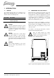
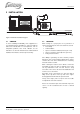
CONTENTS 1 INTRODUCTION 1.1 GENERAL This installation manual applies to the installation of the Whisper Power W-SQ20 generator set in vehicles. This manual is valid for the following models: Part number 41101320 41101326 Description W-SQ20 230V/400V 1500rpm Mobile W-SQ20 230V/400V 1500rpm Mobile -ungrounded For other models see our website: www.whisperpower.eu.
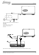
INTRODUCTION Figure 2: Typical vehicle application radiator top mounted 4 Figure 3: Typical vehicle application radiator bottom mounted April 2010 / W-SQ20 for mobile applications / EN
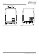
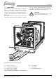
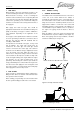
INSTALLATION 2 INSTALLATION Figure 4: Schematic installation diagram 2.1 GENERAL To ensure reliability and durability of the equipment, it is very important that the installation is carried out with the utmost care and attention. To avoid problems, such as temperature problems, noise levels, vibration, etc. the instructions set out in this manual must be followed and all installation work must be carried out professionally. 2.
INSTALLATION 2.3 INSTRUCTIONS FOR OPTIMAL SOUND AND VIBRATION INSULATION Position the generating set as low as possible in the vehicle. The generating set is already secured to the base frame by means of flexible engine mountings. The base frame is mounted to the chassis of the vehicle on a second set of rubber mountings that is included in the delivery. Use the included mounting template to determine the mounting spots.
INSTALLATION 2.5 CONNECTIONS The generating set comes with all supply lines and output cables (i.e. electric cables, coolant connections, exhaust, fuel lines etc.) already connected to the engine and generator. The supply lines are fed through the capsule’s front base. The connections are marked as shown in figures 7 till 10. All electrical connections, cable types and sizes must comply with the appropriate national regulations. Supplied cables are rated for ambient temperatures up to 70°C.
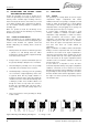
INSTALLATION 2.5.1 Fuel supply 1 FUEL TANK Fuel tanks should be made of appropriate material such as (stainless) steel or plastic. Steel tanks should not be galvanised or painted inside. Condensation can occur in metal tanks when temperature changes. Therefore, water accumulates at the bottom of the tank and provisions should be made for the drainage of this water.
INSTALLATION 1 2 5 A 3 4 Figure 8 Fuel supply (fuel tank is below the generating set) 1 Fuel return 2 Fuel supply 3 Prefilter / Water separator (optional) 4 Extra fuel lift pump (optional) 5 Fuel tank Figure 9: Fuel line assembly with vertical mounted additional pump and fuel lift pump mounted in an angle EN/ W-SQ20 for mobile applications / April 2010 9
INSTALLATION 3 FUEL PIPES When the tank is above the generating set (figure 7) we recommend ending the return line on the top of the tank. When the return is on the top - in case of a leakage the return line cannot overflow because of siphoning. One will only need a fuel cock in the fuel supply line. When the tank is below the generating set we recommend ending the return line on the bottom of the tank (A) below the inlet of the supply line.
INSTALLATION Special attention should be paid to the ventilation of the system. Each installation system is standard supplied with an expansion tank for the coolant, which is also used to release air bubbles and makes it possible to add coolant into the system in an easy way. This expansion tank should be at the highest point of the system and mounted as high as possible.
INSTALLATION It is very important to use good quality heat resistant hose and fittings. Therefore it is strongly advised to use Whisper Power installation kits. 2 HOW AND WHERE TO MOUNT THE RADIATOR The radiator kit includes rubber mountings to prevent vibrations to be transferred to the body of the vehicle (figure 15). Due to the difference between vehicles general instructions are not available. One has to find out where the best place for mounting is.
INSTALLATION Roof mounted radiators 2.5.3 The radiator on the roof is often the best option from the point of view of keeping the noise of the fans away from people and it will give the best result in dissipating the heat. However, often this option conflicts with the possible need to keep the vehicle as low as possible. An other disadvantage is that the piping has to go through the roof which requires provisions to be waterproof.
INSTALLATION A negative feature of a dry exhaust system is the heat radiated by its components. Measures are taken to overcome the heat problem: The exhaust bent to bring the exhaust out of the canopy is cooled by water. Insulation blankets are included in the exhaust kit to insulate the flexible bellow and the first muffler. When a dry exhaust has its outlet on the roof, all the pipes inside the vehicle has to be insulated.
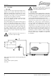
INSTALLATION 2.5.4 Electrical installation (12 Volt) 1 DIGITAL DIESEL CONTROL SYSTEM The electrical control system is standard in 12 Volt with negative earth. Non- earth return is available as an option. All electrical wiring has been prepared on the generating set to the control panel prior to despatch from the factory. The engine is controlled by a very advanced microprocessor based system: Digital Diesel Control. The “black box” containing the microprocessor is located on top of the alternator.
INSTALLATION by an emergency switch or a potential free fire alarm switch with normally closed contacts Remove bypass between J7 - J18 local control panel (rear view) Normal operation Alarm / emergency Fig. 25: Connection for emergency stop / fire alarm switch Automatic starting and stopping Automatic start/stop Whisper Power cannot be held responsible for damage caused by the unattended running generator using the autostart/stop mode or interval mode.
INSTALLATION IVO SMART 12/10. A battery switch and a charger are included in the battery installation kits, art. no. 40230220 (160Ah) 3 OTHER RECOMMENDATIONS AND WARNINGS The battery should be secured for poor road conditions and the terminals should be insulated. For extra safety the battery can be enclosed in a wooden, plastic, fiberglas etc. (non metal) box. Even when the earth return system is applied a negative battery cable should be used and the vehicle should not to be used as a conductor.
INSTALLATION 1 FUSE An output fuse (between the generating set and the electrical installation) should be installed to protect the installed electrical system. For the W-SQ20 the maximum single phase current at 230V is 108 Amps. Using three phases the fuses should be three times 36 Amps and mechanically connected. The fuses must be of the slow reacting type. For electrical motors connected to the system, a motor protection switch must be installed 2 GROUNDING The AC alternator windings are not grounded.
INSTALLATION SPECIFICATIONS 3 INSTALLATION SPECIFICATIONS 3.1 1 GENERAL Install the generating set on the 4 anti vibration mounts. Use the template included in the shipment to drill the 8 mounting holes. 3 4 5 6 7 8 9 ANTIVIBRATION MOUNTS 10 Figure 27: Anti-vibration mounts 2 3 4 Mount the cooling system for the engine Connect exhaust system. Connect ‘fuel supply line’ to the water separator/ fuel filter. 5 Connect ‘fuel return line’ to the fuel tank. 6 Connect remote panel (just plug in).
INSTALLATION SPECIFICATIONS 3.3 TECHNICAL DATA W-SQ20 Dimensions incl. sound shield. 126 x 68 x 80 cm (L x W x H) Dimensions w/o. sound shield. 115 x 60 x 75 cm (L x W x H) Weight incl. sound shield 580 kg Weight w/o. sound shield 480 kg Max. operation angle 25° Remote panel 15 m cable Digital Diesel Control System Battery capacity min.
INSTALLATION SPECIFICATIONS 3.
INSTALLATION SPECIFICATIONS Figure 28.
INSTALLATION SPECIFICATIONS RADIATOR COOLER KIT ENGINE 230VAC W-SQ20 no qty article no description 1 1 50230511 Radiator AP 130EB 230 VAC 2 2 50221502 Hose clamp stainless 22-30 3 1 50221064 “Male nipple 1” 4 1 50221044 TEE-fitting-1” 5 2 50221014 Male hose connection 1”x35 6 1 50221103 “Straight reducer m/f 1”-3/4” 7 1 50221004 Male hose connection 3/4x20 8 1 50212409 Temperature switch 87-82 degr 14 6m 50220013 Cooling water hose smooth (1 1/4”) 32x41mm 15 4 50221504 Hose clamp stainless 35-50mm 16 8 502
INSTALLATION SPECIFICATIONS Figure 29: radiator cooling kit engine and exhaust kit 24 April 2010 / W-SQ20 for mobile applications / EN
INSTALLATION SPECIFICATIONS Figure 30: Installation materials rubber mounting kit EN/ W-SQ20 for mobile applications / April 2010 25
DIAGRAMS & DRAWINGS 4 DIAGRAMS & DRAWINGS LAYOUT GENERATOR CONTROL FOR W-SQ20 WITH 230VAC FAN Optional control for two speeds fans. See chapter 4.5 4.
DIAGRAMS & DRAWINGS 4.
DIAGRAMS & DRAWINGS 4.3 GENERATOR DIAGRAM 3 PHASE WITH AVR 230V – 400V 50HZ WITH AVR * TO CONNECT NEUTRAL TO GROUND * TO CONNECT NEUTRAL TO GROUND REFER 2.1.3 USER MANUAL W-SQ2025U REFER TOTO 2.1.
DIAGRAMS & DRAWINGS 4.4 AC WIRING DIAGRAM SINGLE PHASE WITH AVR 230V HZ (DOUBLE DELTA) * TO CONNECT NEUTRAL TO GROUND *REFER TO CONNECT NEUTRAL TO GROUND TO 2.1.3 USER MANUAL W-SQ20 REFER TO 2.1.
DIAGRAMS & DRAWINGS 4.5 ELECTRICAL DIAGRAM RADIATOR FAN CONTROL 230VAC Fig. 35: Electrical diagram for standard fan control using a 230V AC radiator fan JUNCTION BOX AIR FANS TRAFO 230/115VAC 200VA 12VDC K1 K2 230VAC DIMENTION BOX: 270x270x180 MM Fig.
DIAGRAMS & DRAWINGS 4.6 REMOTE CONTROL PANEL DRAWINGS Fig.
DIAGRAMS & DRAWINGS 4.7 W-SQ20 DIMENSIONS AND FOOTPRINT Fig. 38 W-SQ20 dimensions and footprint CONNECTIONS W-SQ20: • exhaust: 2” • fuel hose: 8 mm • coolant in/out: Ø 35 mm • battery +: 35 mm2 • battery -: 35 mm2 POWERCABLES • W-SQ20 230V single phase (108 Amps) 3x25 mm2 (not included) • W-SQ20 230/400V 3 phases (3x 36Amps) 5x6 mm2 (not included) REMOTE CABLE (ALL MODELS) • 8 wire communication cable, 15 meter (included). For longer lengths (max.
NOTES NOTES: EN/ W-SQ20 for mobile applications / April 2010 33
NOTES NOTES: 34 April 2010 / W-SQ20 for mobile applications / EN
NOTES NOTES: EN/ W-SQ20 for mobile applications / April 2010 35
Kelvinlaan 82, 9207 JB Drachten, The Netherlands Tel : + 31-512-571550 / Fax : + 31-512-571599 www.whisperpower.eu / info@whisperpower.