
Installation manual


INSTALLATION
EN/ W-SQ20 for mobile applications / April 2010 15
2.5.4 Electrical installation (12 Volt)
1 DIGITAL DIESEL CONTROL SYSTEM
The electrical control system is standard in 12 Volt with
negative earth. Non- earth return is available as an option.
All electrical wiring has been prepared on the generating
set to the control panel prior to despatch from the factory.
The engine is controlled by a very advanced
microprocessor based system: Digital Diesel Control.
The “black box” containing the microprocessor is located
on top of the alternator.
A local control panel is on the generating set.
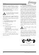
Remote control
A remote control panel also containing a microprocessor is
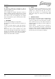
in the delivery. A 15 m intermediate 8-pole communication
cable is in the standard supply as well (refer to figure 23).
If necessary an optional longer (up to 30m / 100ft)
intermediate cable can be connected if the standard length
does not suit the required distance. When a longer
distance than 30m / 100ft is required, consult the Whisper
Power service department for advice.
Figure 23 Remote control cable
One can mount the control panel after drilling a hole in the
dashboard using the plastic cover. Refer to the
dimensional drawings in chapter 4. The panel without the
plastic cover fits the Mastervision modular panel system.
More remote control panels (slave panels) can be put in
parallel by using the modular connectors on the back of
the units. As a slave one can use the same panel offering
all functions again. It is also possible to use an old or new
type slave panel only to start and stop the generator.
Old type remote panels and system panels can be
connected by means of the green connector.
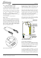
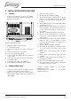
When using the factory settings, installation is very simple:
just plug the remote cable into the remote and the
generator is ready to use. Refer to figure 24.
WIRING COLOURS
RED
GREEN
BROWN
YELLOW
PI NK
PURPLE
BL UE
WHITE
GRE Y/ P IN K
GRE Y
RED/ BLUE
BLACK
MAX. 150 mA
WARNING RELAY
REMOTE CABLE
REMOTE CABLE
2
1
5
4
3
8
7
6
11
10
9
12
SENSE BAT. 2
121110987654321
Whisper Remote Panel
WRP/ 2
J3
Figure 24 Remote box terminals
Acoustic alarm or warning lamp
One can connect an external max.150 mA relay to
generate an acoustic warning or applying a warning lamp
etc. Be aware of polarity as some relays has a diode
inside and should be connected plus to plus en minus to
minus as indicated. Refer to figure. 24.
Connection for emergency stop / fire alarm switch
To connect an emergency stop button or to stop the
generator automatically in case of a fire alarm, you can
use the bypass connection between fastons J7 and J18 on
the backside of the local control panel. See figure 25. To
do so, remove this bypass connection and then replace it