INSTALLATION MANUAL M-SQ20 / 25 - 1500 RPM - Marine diesel generating set 230/400V / 50Hz Digital Diesel Control Art.nr. 40200451 WHISPER POWER BV Kelvinlaan 82 9207 JB Drachten Netherlands Tel.: +31-512-571550 Fax.: +31-512-571599 www.whisperpower.eu V1.
CONTENTS CONTENTS: 1 INSTALLATION ............................................................................................................................................................... 3 1.1 General .............................................................................................................................................................. 3 1.2 Location ................................................................................................................................
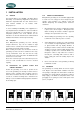
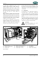
INSTALLATION 1 INSTALLATION 1.1 General 1.3.1 Further recommendations This manual applies to the M-SQ20 / 25 Marine Diesel Generating set controlled by Digital Diesel Control first launched in September 2005. For other models refer to other manuals available on our website: www. whisperpower.eu. WhisperPower generating sets are standard equipped with a sound cover. The canopy has been designed to give effective sound insulation.
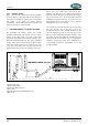
INSTALLATION A "sealed" engine compartment must have a good extraction ventilator to maintain reasonable engine room temperatures. High temperature of intake air reduces engine performance and increases engine coolant temperatures. Air temperatures above 40°C reduce the engine power by 2% for each 5°C of rise. To minimise these effects the engine room temperature must not be more than 15ºC above the outside ambient air temperature.
INSTALLATION 1.5.1 1 Fuel supply FUEL TANK Fuel tanks should be made of appropriate material such as (stainless) steel or plastic. Steel tanks should not be galvanised or painted inside. Condensation can occur in metal tanks when temperature changes. Therefore, water accumulates at the bottom of the tank and provisions should be made for the drainage of this water.
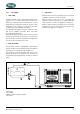
INSTALLATION 1 2 5 A 3 4 Fig. 4 Fuel supply 1 Fuel return 2 Fuel supply 3 Prefilter / Water separator (optional) 4 Extra fuel lift pump (optional) 5 Fuel tank Both supply and return fuel pipe lines should be appropriate material and 8 mm outer diameter tubing. The quality of the tubing of fuel pipes could be submitted to local regulations depending on the application of the vessel.
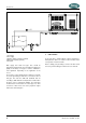
INSTALLATION 1.5.2 Cooling Intercooling is based on a raw water pump, heat exchanger and water-injected exhaust. Cooling liquid in the internal cooling system is cooled in a heat exchanger by outboard water (raw water or seawater). After the raw water is warmed up in the heat exchanger it is dumped overboard by injecting it in the exhaust. The generating set should have its own sea water (coolant water) inlet and should not be connected to any other engine systems.
INSTALLATION 2 RAW WATER SUPPLY For raw water supply the following installation materials are required: -a skin fitting - a sea cock - a water strainer hoses and clamps. In order to keep the suction resistance in the line at a minimum, the sea water intake system (i.e. sea cock, trough-hull fitting, inlet filter, etc.) must have an inner diameter of at least 25.4 mm diameter (1"). The suction hose should be kept as short as possible. Raw water plumbing should avoid bends as much as possible.
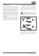
INSTALLATION 4 WATER STRAINER OPEN Use an appropriate water strainer with connections of 25.4 mm (1"). Install the water strainer in a well accessible position, 5 cm above the waterline (see fig. 6, ref. 6). 5 SIPHON BREAKER (AIR VENT) When the point of water injection is below the waterline, then -when the engine is stopped -there is a risk that the cooling water may enter the engine as a result of siphoning.
INSTALLATION 1.5.3 Exhaust system Water is injected in the exhaust system of the generating set. In this way the cooling water that has passed the heat exchanger is mixed with the exhaust gases. Temperature and volume of the gases are thereby reduced considerably, so that a rubber exhaust hose can be used and the level of noise is reduced as well.
INSTALLATION 2 "SUPER SILENT" EXHAUST SYSTEM If the through-hull exhaust outlet has to be mounted far from the generating set an exhaust/water separator must definitely be installed (Total length of the exhaust piping from generator to top of goose neck (water separator) is more than 3 m.) (ref. to fig. 12). 24" 60cm In order to reduce the noise level of the generating set to a minimum, an option to reduce the exhaust noise further (especially exhaust water splashing) is an exhaust/water separator.
INSTALLATION However water traps should be avoided as the fumes still contains water and this should not accumulate in bents (see fig 13). An additional outlet exhaust muffler close to the hull outlet will help further to reduce noise emission (figure 10, ref. 2) If the generating set and the exhaust system have been installed correctly, neighbouring boats will not be disturbed by generating set noise. With the "super silent" exhaust system, generating set noises are almost inaudible.
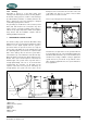
INSTALLATION 1.5.4 1 Digital Diesel Control system (12 Volt) DIGITAL DIESEL CONTROL SYSTEM The electrical control system is standard in 12 Volt with negative earth. Non- earth return is available as an option for aluminium vessels to prevent corrosion. All electrical wiring has been prepared on the generating set to the control panel prior to despatch from the factory. The engine is controlled by a very advanced microprocessor based system: Digital Diesel Control.
INSTALLATION Acoustic alarm or warning lamp Automatic start/stop One can connect an external max.150 mA relay to generate an acoustic warning or applying a warning lamp etc. Be aware of polarity as some relays has a diode inside and should be connected plus to plus en minus to minus as indicated. Refer to fig. 16.
INSTALLATION 2 STARTER BATTERY For starting, the WhisperPower requires a battery with a capacity of at least 120 Ah. The generating set can be connected with the main engine battery or have its own battery. We strongly recommend the use of a separate battery for the generating set and to keep the wiring system for the propulsion engine and the domestic DC supply system completely separate and individually connected to separate batteries.
INSTALLATION 1.5.5 AC power system (230 / 400 Volt) Before working (installation) on the system read the sections on safety in the users manual. Be sure that all electrical installations (including all safety systems) comply with all required regulations of the local authorities. All electrical safety/shutdown and circuit breaking systems have to be installed onboard as the generating set itself cannot be equipped with such equipment for every possible variation.
INSTALLATION SPECIFICATIONS 2 INSTALLATION SPECIFICATIONS 3 2.1 1 General Install the generating set on the 4 anti vibration mounts. Use the template included in the shipment to drill the 8 mounting holes. 4 5 6 7 8 ANTIVIBRATION MOUNTS 9 Fig. 19 Antivibration mounts 2 3 4 Connect the (sea) water inlet to the strainer. Connect exhaust system. Connect a siphon breaker or ‘air vent’ into the cooling circuit, if necessary. 5 Connect ‘fuel supply line’ to the water separator/ fuel filter.
INSTALLATION SPECIFICATIONS 2.3 Installation specifications M-SQ20 / 25 TECHNICAL DATA Dimensions incl. sound shield. Dimensions w/o. sound shield. Weight incl. sound shield Weight w/o. sound shield Max. operation angle Remote panel 15 m cable Battery capacity min.
INSTALLATION SPECIFICATIONS 2.
INSTALLATION SPECIFICATIONS WATER SEPARATOR KIT 63 mm no qty article no 21 2 50221541 22 2 50221542 23 2.5 50220036 40 1.
INSTALLATION SPECIFICATIONS Fig.
INSTALLATION SPECIFICATIONS Fig.
INSTALLATION SPECIFICATIONS Fig.
INSTALLATION SPECIFICATIONS Fig. 23 Installation materials water inlet and air vent * Hose drain should go downwards. Water must flow out freely. Refer to installation manual for proper installation air-vent kit.
DIAGRAMS & DRAWINGS 3 DIAGRAMS & DRAWINGS 3.1 DC wiring diagram Fig.
INSTALLATION SPECIFICATIONS 3.
DIAGRAMS & DRAWINGS 3.3 AC wiring diagram Tri-Phase with AVR 230V / 400V 50Hz (Star) * TO CONNECT NEUTRAL TO GROUND * TO CONNECT NEUTRAL TO GROUND REFER TO 2.1.3 USER MANUAL M-SQ20 / REFER TO 2.1.
INSTALLATION SPECIFICATIONS 3.4 AC wiring diagram Single Phase with AVR (Double Delta) **TO NEUTRALTO TO GROUND TOCONNECT CONNECT NEUTRAL GROUND REFER 2.1.3 USER USERMANUAL MANUALWHISPER M-SQ20 /25U 25 REFER TO 2.1.
DIAGRAMS & DRAWINGS 3.5 WhisperPower remote panel Fig.
INSTALLATION SPECIFICATIONS 3.6 M-SQ20 / 25 dimensions and footprint Fig. 30: M-SQ20 / 25 dimensions and footprint CONNECTIONS M-SQ20 / 25: • exhaust: 63 mm 2 1/2” • fuel hose: 8 mm • water inlet: 25 mm (1”) • battery +: 35 mm2 • battery -: 35 mm2 POWERCABLES • M-SQ20 / 25 230V single phase (108 Amps) • M-SQ20 / 25 230/400V 3 phases (3x 36Amps) 3x25 mm2 (not included) 5x6 mm2 (not included) REMOTE CABLE (ALL MODELS) • 8 wire communication cable, 15 meter (included). For longer lengths (max.
NOTES: EN / M-SQ20 / 25 / Oktober 2010 31
Kelvinlaan 82, 9207 JB Drachten, Netherlands Tel : + 31-512-571550 / Fax : + 31-512-571599 www.whisperpower.eu / info@whisperpower.