
Installation manual

INSTALLATION
4 Oktober 2010 / M-SQ20 / 25 / EN
A "sealed" engine compartment must have a good
extraction ventilator to maintain reasonable engine room
temperatures. High temperature of intake air reduces
engine performance and increases engine coolant
temperatures. Air temperatures above 40°C reduce the
engine power by 2% for each 5°C of rise. To minimise
these effects the engine room temperature must not be
more than 15ºC above the outside ambient air
temperature.
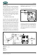
Apply a combination of ventilators, blowers and air intake
ducting to meet the temperature limit. The air inlet ducts
should run to the bottom of the engine room to clear fumes
from the bilge and to circulate fresh air. Air outlets should
be at the top of the engine room to remove the hottest air.
An engine room blower should be used as an extraction
ventilator to remove air from the engine room.
In cases where it is impossible to meet the above
mentioned temperature limit by using machine room
ventilation, connections are to be made for an air inlet
directly to the enclosure. With these connections the
generating set can be directly connected to an air duct.
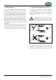
Air inlets should be louvered, where appropriate, to protect
the engine room and to protect the generating set from
water spray. As an extra precaution, the fitting of a cowl
ventilator with a cover box located as high as possible, is
recommended.
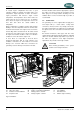
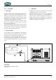
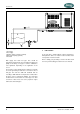
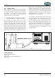
1.5 Connections
The generating set comes supplied with all supply lines
and output cable (i.e. electric cables, cooling water
connections, exhaust, fuel lines etc.) already connected to
the engine and generator. The supply lines are fed through
the capsule’s base. The connections are marked as shown
in fig. 2.
All electrical connections, cable types and sizes must
comply with the appropriate national regulations. Supplied
cables are rated for ambient temperatures up to 70°C. If
the cables are required to meet higher temperature
requirements, they must be run through conduits.
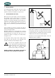
ATTENTION!
Before working (installation) on the system
read the section safety instructions
01 Remote control 05 Bypass cooling water out Ø25.4mm 09 Fuel out Ø8mm
02 AC power output 06 Bypass cooling water in Ø25.4mm 10 Fuel in Ø8mm
03 Exhaust connection Ø63mm 07 Battery positive + 35mm2 11 Raw water inlet
04 Expansion tank 08 Battery negative - 35mm2 12 Rubber engine mounting
Fig. 2 Connections