
Installation manual

INSTALLATION
EN / M-SQ20 / 25 / Oktober 2010 9
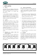
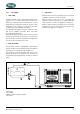
4 WATER STRAINER
Use an appropriate water strainer with connections of 25.4
mm (1"). Install the water strainer in a well accessible
position, 5 cm above the waterline (see fig. 6, ref. 6).
5 SIPHON BREAKER (AIR VENT)
When the point of water injection is below the waterline,
then -when the engine is stopped -there is a risk that the
cooling water may enter the engine as a result of
siphoning. To avoid this happening, the generating set is
designed to accommodate a siphon breaker (air vent). See
figure 2. In the standard delivery the connections are
bypassed. Hose of 25.4 mm (1") inner diameter should be
used.
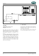
If the generating set cannot be mounted such that the
bottom of the generating set is placed above the waterline,
an air vent must be installed.
Extend the water hose of the by-pass 60 cm above
waterline and install an air vent. Ideally, the air vent should
be mounted above the yacht keel center line (i.e. to
minimize the influence of swaying on the water intake).
See figure 6, ref. 5.
Fast motorboats will lay deeper when sailing at large
speed and can cause pressure on the waterinlet. This
should be avoided to prevent fleeding the engine.
If the air vent is clogged the water hoses will
not be vented when the generating set has
stopped and water can be forced into the
engine. This leads to immediate engine
problems and eventually severe damage!
DAMAGE CAUSED BY THE INGRESS OF WATER IN
THE ENGINE IS NOT COVERED BY GUARANTEE
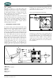
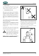
OPEN
Fig 8: Wrong siphon breaker hose routing
On the valve is a little hose to drain a little water that could
be spilled from the valve. See figure 8. This hose should
go down and may not end under water, because it should
ventilate air into the valve to break the siphoning.
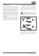
Check the air vent at regular intervals. Open, clean and
lubricate the valve as required.
OPEN
Fig. 9 WhisperPower siphon breaker