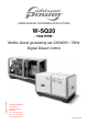
USERS MANUAL FOR MOBILE APPLICATIONS W-SQ20 - 1500 RPM - Mobile diesel generating set 230/400V / 50Hz Digital Diesel Control Art.nr. 40200626 WHISPER POWER BV Kelvinlaan 82 9207 JB Drachten Nederland Tel.: +31-512-571550 Fax.: +31-512-571599 www.whisperpower.
CONTENTS CONTENTS: 1 INTRODUCTION .............................................................................................................................................................. 4 1.1 General .............................................................................................................................................................. 4 1.2 Service and maintenance ..................................................................................................................
CONTENTS 3 OPERATION .................................................................................................................................................................. 21 3.1 General ............................................................................................................................................................ 21 3.2 Operating Instructions ............................................................................................................................
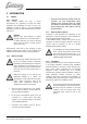
INTRODUCTION 1 INTRODUCTION 1.1 GENERAL DANGER This danger symbol refers to electric danger and draws attention to special warnings, instructions or procedures which, if not strictly observed, may result in electrical shock which will result in severe personal injury or loss of life. The W-SQ20 Mobile Diesel Generating set is manufactured and marketed by Whisper Power. It is important to read this manual before installing and operating the generating set.
INTRODUCTION and the radiator fan sucking exhaust gasses into the radiators. The generator and other parts should be protected against the influences of the weather and splashing water (with dirt and salt) below the vehicle. Refer to the installation manual for instructions but remember these are for guidance only as many factors influence the installation of a generator. The ultimate responsibility will always be with the owner to ensure a safe and compliant installation.
INTRODUCTION 1.5.2 Identification plate All required identification data are on the identification plate. For location of the identification plate see figure 1 1 2 3 4 5 6 7 Fig. 1: Identification plate. Fig. 2: Location identification plate. 6 The identity of the generating set is given by the SERIAL NUMBER. When this number is available the manufacturer can trace the specifications of the generating set.
INFORMATION 2 INFORMATION 2.1 SAFETY 2.1.1 General • When correctly installed and used in normal circumstances this generating set fulfils EC safety regulations. This generating set could be part of an installation or could be used in a way that additional regulations of the EC or other authorities have to be taken into account. 2.1.
INFORMATION 2.1.5 Operation External moving parts like fans and V-belts are covered by the soundshield and therefore the W-SQ20 is very safe when the soundshield is closed. • Keep a fire extinguisher on hand. Nevertheless take note of the signs on the generating set which show symbols in a triangle indicating danger. BREAK THROUGH HERE When service has to be carried out while the engine is running, be aware of moving parts like V-belts.
INFORMATION 2.3 • 2.2 Engines may be fitted with seals or O-rings manufactured from "viton" or similar material. When exposed to abnormal high temperatures in excess of 400°C an extremely corrosive acid is produced which cannot be removed from the skin. If signs of decomposition are evident, or if in doubt, always wear disposable heavy duty gloves. TRANSPORT, LIFTING AND STORAGE When lifting the generating set avoid any risk of personal injuries, do not stand under the generating set.
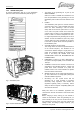
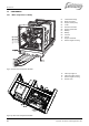
INFORMATION 2.4 2.4.1 COMPONENTS Main components to identify 01 02 03 04 05 06 07 08 09 10 11 12 Thermostat housing Boiler connection Engine coolant pump V-belt Exhaust connection Engine coolant OUT Battery + Battery Fuel out Fuel in Engine coolant IN Rubber engine mounting 15 16 17 18 Filler cap engine oil Filler cap engine coolant Rubber engine mounting Rocker cover Fig. 4: Left View main components W-SQ20 Fig.
INFORMATION 19 20 21 22 23 24 25 26 27 28 29 30 31 32 33 34 35 Hoist eye rear Engine speed adjusting screw Fuel injector Glowplug (4x) Fuel filter Fuses Control panel Air cleaner element Indentification plate Oil sump handpump Coolant drain plug Engine oil dipstick Fuel solenoid Oil filter Injection pump air bleeding screw Fuel lift pump for manual priming Fuel injection pump Fig. 6 Front View main components W-SQ20.
INFORMATION 2.4.2 Generator control panel 2.5 2.5.1 Start / Stop Internal fuel pump Digital Diesel Control Fuse 3A Fuse 3A Remove fuse before maintenance Auxiliary Fuse 10A External Fuel Pump Fuse 3A Whisper Digital Diesel Operation Unit Observe instructions in the manual Replace fuses with same type and rating Fig: 8 Control panel. Fig. 9 Digital Diesel Control unit 2.4.
INFORMATION 2.5.3 Digital Diesel Control system The standard electrical engine control system is 12 Volt negative earth, non earth return (ungrounded) is available as option. Check your identification data to determine which system is applied. The system is designed according to the "energise to run" system. The Digital Diesel Control is a very advanced microprocessor based full automatic system. Besides automatic start the system offers many monitoring options.
INFORMATION 2.5.8 Remote control All wiring connections from the remote control to the board are made by plug in connectors. An intermediate communication cable is in the standard supply. If necessary an optional longer 8 wire communication cable can be connected if the standard length does not suit the required distance. Numerous remote control units can be put in parallel by using the connectors on the back of the units.
INFORMATION 2.5.
INFORMATION Optional control for two speeds fans. See chapter 4.8 2.5.15 Electrical diagram control wiring W-SQ20 Fig.
INFORMATION 2.5.16 Terminal modes 115VAC – 230VAC - 400VAC 50Hz Fig.
INFORMATION 2.5.17 Generator Diagram 3 phase with AVR 230V – 400V 50Hz with AVR * TO CONNECT NEUTRAL TO GROUND REFER TO 2.1.3 USER MANUAL W-SQ20 * Fig 15.
INFORMATION 2.5.18 AC Wiring Diagram single phase with AVR 230V Hz (Double Delta) TOCONNECT CONNECT NEUTRAL GROUND ** TO NEUTRAL TOTO GROUND REFERTO TO 2.1.3 USER MANUAL W-SQ2025U REFER 2.1.3 USER MANUAL WHISPER Fig 16.
INFORMATION 2.5.19 Electrical diagrams radiator fan control Fig. 17: Electrical diagram for standard fan control using a 230V AC radiator fan JUNCTION BOX AIR FANS TRAFO 230/115VAC 200VA 12VDC K1 K2 230VAC DIMENTION BOX: 270x270x180 MM Fig.
OPERATION 3 OPERATION 3.1 GENERAL The generating set is operational after full installation and filling up with: fuel, engine lubricating oil and cooling liquid, connecting the battery to earth and connecting the digital remote control panel. 1 2 Maximum oil level Minimum oil level 1 2 Fig. 19: 3.2 3.2.1 In operation checks: 1 Check for abnormal noise or vibration 2 Check the voltage 3 Power source selector switch (off/external power/generator power). Switch to power source generator.
OPERATION 2 3 4 5 Check coolant in the expansion tank. Check for leakages. If no Mass Systemswitch is used: Switch main Power Source Selector switch to "OFF" or switch off all devices. Switch on the battery switch. Starting the generator: By pushing the start button briefly the electric system is activated and the starting procedure will begin (by pushing the Stop button the system is deactivated). The first time starting up or after running out of fuel it could be necessary to prime the fuel system.
MAINTENANCE 4 MAINTENANCE 4.1 ALTERNATOR The alternator does not require any maintenance. Periodic inspection and cleaning is recommended, depending on environmental conditions. However when the alternator has been idle for a long period attention to winding condition is recommended. The condition of windings can be assessed by measurement of insulation resistance to earth (see section 5.3.5, Meggering). The alternator bearing is greased for life and is therefore not regreasable 4.2 4.2.1 4.2.
MAINTENANCE 4.2.4 Replacing fuel filter Filter change depends on contamination of the fuel, but should be done however, at least every 300 running hours. A clogged filter results in a lack of output of the generating set. A smeer of oil has to be put on the seal of the filter before fitting the filter. The filter should be fastened manually: when the rubber touches the metal turn 3/4 further. Fig. 23 01 4.2.6 01 Fuel filter Fig. 21 Location fuel filter cartridge 4.2.
MAINTENANCE 4.3 REGULAR MAINTENANCE AFTER FIRST 300 HOURS: • Retighten the cylinder head bolts and adjust the valve clearance. (Refer to § 5.4.2). CHECK DAILY: • Oil level (see fig. 26) EVERY 300 HOURS: • Check the impeller of the engine coolant pump. • Replace the oil filter. • Replace the fuel filter Replacement depends or the condition of the fuel. We recommend replacement every 300 hours. Take care the oil level is never below the mark.
MAINTENANCE 4.3.1 Maintenance schedule 4.3.2 Check oil level daily Check the level of the cooling liquid daily Hoses for loose connections or deterioration daily Change oil and oil filter after first 50 hours Check and tighten nuts, bolts, etc.
TROUBLE SHOOTING 5 TROUBLE SHOOTING 5.1 ALTERNATOR/ ELECTRICAL FAULTS Beware of parts which are live! Remove 3 Amp. Fuse in the control panel while working on the generator to prevent the engine from starting A failure code is displayed when a hardware failure at the generator is detected 5.1.1 General If any problem should occur, check basic conditions and examine all external wiring, switch gear and circuit breakers. Also check if measuring instruments give the correct value.
TROUBLE SHOOTING PROBLEM than 225V between phase and neutral). CAUSE • Faulty AVR. When slightly too low, adjustment could be necessary • Defective diode SOLUTION Try to readjust AVR. Check by independent excitation if the problem is in the AVR or in the windings and replace AVR if necessary (see special procedures). Check the diode in the rotor (see special procedures). The W-SQ20 has one diode block/rectifier unit. • When applying 3 phase: an unbalanced load; check the voltage of the other phases.
TROUBLE SHOOTING Failure code COMMUNICATION LOW START BAT ALTERNATOR AC-ALTERN. TEMP WATER TEMP OIL PRESSURE AC VOLTAGE HIGH CURRENT FREQUENCY 5.2.
TROUBLE SHOOTING PROBLEM CAUSE • Choked fuel filter. • Disturbances on the electrical system/ user side. • Faulty fuel lift pump. • Choked air cleaner element. • Lack of air. • Choked exhaust system, exhaust blocked,. • Air in the fuel pipes SOLUTION Check fuel filter and fuel lift pump: clean or replace if necessary. Check if electrical load is fluctuating Try the pump by manual operation.
TROUBLE SHOOTING PROBLEM CAUSE • Excessive heat in cooling system (thermo-switch tripped). • Lack of cooling water (exhaust switch tripped). • Impeller broken. • Cooling water blocked. • Air or water in the fuel. • Blocked air or fuel filter. • Loss of compression by wear out or damage. • V-belt broken or loose. • Thermostat faulty Sooty, black exhaust. • Generator is being overloaded. Digital Diesel Control will indicate “HIGH CURRENT”. • Insufficient intake air. • Choked air cleaner element.
TROUBLE SHOOTING 5.2.4 Service address If you cannot correct a problem with the aid of the malfunction table, contact your Whisper Power Service Centre or Whisper Power Netherlands for an extended service list, tel: INT +31-512-571550.
TROUBLE SHOOTING 5.3 5.3.1 SPECIAL PROCEDURES ALTERNATOR Automatic Voltage Regulator (AVR) The voltage regulator has a ±2% voltage precision in the machine working range with distortion free loads. The phase voltage can be adjusted by trimmer “V” (see figure 27) from 185 to 290V. The regulator is equipped with a frequency dependant excitation limiter; the frequency can be calibrated by trimmer “UF”, which is factory set at 46Hz (56Hz), ±1Hz.
TROUBLE SHOOTING Fig.28 Residual voltage check / excitation procedure. When using the starter battery fuse it and limit the current with a 30 Ohm resistor. Flashing can be done while the engine is running and the wiring is connected. When a variac (variable power supply) is available one should be able to control the voltage manually. CAUTION If the starter set battery is used for exciting one must take care. A short circuit can cause heavy sparking, fire and injuries.
TROUBLE SHOOTING 5.4 5.4.1 SPECIAL PROCEDURES ENGINE Setting the RPM RPM is set by the manufacturer and should not need readjustment! However a very slight offset after running in could occur. RPM can be measured by a frequency meter. Before readjustment check any other explanation for the wrong speed. Engine speed is set at the factory at nominal 1500 (50 Hz) RPM. A RPM drop of 5% at full load is acceptable. Therefore a no load setting should be at ± 1575 RPM = 52.5 Hz.
TROUBLE SHOOTING 360° in the direction of engine rotation again. No. 1 piston is now at T.D.C. of the compression stroke. After adjusting the valves of cylinder 1 adjust the valve clearance of the remaining cylinders in firing order 1-3-4-2 Turn the crankshaft 180º clockwise from the T.D.C of cylinder 1 to the T.D.C of cylinder 3. Adjusts the valves of cylinder 3 and turn the crankshaft further clockwise to the T.D.C of cylinder 4 and finally to 2. 5.4.
TROUBLE SHOOTING 3 4 To take the generating set out of the canopy all hose and cable connections have to be taken off. The set is fixed to its base by four rubber mountings and can be loosened by removing the four nuts from the bolts of these mountings.
SPARE PARTS LIST 6 SPARE PARTS LIST A complete parts manual in English is available as an option number: number: 40200187 (***) A work shop manual in English is available as an option number: 40200174 (***). We recommend the following spares for service and maintenance. • Kit A: parts for regular maintenance parts marked (*) • Kit B: parts for maintenance + spare parts: all parts marked (*)+(**) article no. 40201560 article no.
MAINTENANCE LOG MAINTENANCE LOG first service after 50 hours: hour counter: next service (every 150 hours) hour counter: EN / W-SQ20 for mobile applications / April 2010 remarks 39
Kelvinlaan 82, 9207 JB Drachten, The Netherlands Tel : + 31-512-571550 / Fax : + 31-512-571599 www.whisperpower.eu / info@whisperpower.