OWNER’S MANUAL Pro-1200W, Pro-1600W Pro-2000W, Pro-2500W Pro-3000W POWER INVERTERS
FEATURES 1. Three 110 AC Outlets 2. Remote Operation Jack The inverter is designed to be operated from a remote location via a WHISTLER Remote Control Switch (P/N Pro-RS01) which plugs into this socket. This optional accessory is available through WHISTLER or your WHISTLER dealer. 3. USB Power Port This port is always on and independent of the inverter’s on/off switch. 4. On/Off Switch Turns the unit On/Off. 5. Digital Power Meter 6.
IMPORTANT INFORMATION Important Information About Your New Whistler Inverter. This manual will provide you with directions for the safe and efficient operation of your Whistle Power Inverter. Read the manual carefully before using your new Whistler inverter and keep the manual on file for future reference. Important Note: Each of the following operating procedures and safety features must be carefully reviewed and thoroughly understood prior to using the inverter.
INVERTER INFORMATION Don’t Push It. Although your Whistler power inverter has the capacity to provide power output (excess current) equal to approximately two times its rated wattage capacity for a very brief period, it is designed to operate equipment and appliances with start up load wattage ratings no higher than its own maximum continuous wattage rating. For example, the Pro-1200W model has a maximum continuous rating of 1200 watts.
BATTERY/CABLE INFORMATION BATTERY INFORMATION 1. 2. To calculate the Ah of the battery, first determine its "reserve minutes" rating. (Deep cycle marine batteries generally have the highest reserve minute ratings). This rating typically is marked on the battery along with the "Cold Cranking Amps" (CCA) rating. Multiply the reserve minutes rating of the battery by 0.3 to determine the battery approximate Ah rating. A battery with a reserve minutes rating of 166 has an Ah rating of 49.8.
OPERATION CABLE INFORMATION Pro-2000W and Pro-2500W Making the Connection. When the inverter and the battery are set up within three feet of each other, use a minimum of #2 gauge wire to make the connections. Within four to six feet, use a #0 gauge wire (Pro-2000W), #00 gauge for Pro-2500W. At distances between six feet to ten feet, use #000 gauge wires (Pro2000W), #0000 for Pro-2500W connected in parallel to the battery. 1. Make certain that the Power switch is in the OFF (O) position. 2.
OPERATION OPERATION Note: • Loose connections can result in a severe decrease in voltage which may cause damage to the wires and insulation. • Failure to make proper connection between the inverter and the power source will result in reverse polarity. Reverse polarity will blow the internal fuses in the inverter and may cause permanent damage to the inverter. Damage caused by reverse polarity is not covered under the Whistler warranty.
OPERATION • Check frequently to ensure that the input and output connections are secure. Loose connections may damage the inverter, the power source, or may generate excessive heat. To generate the maximum output, the Pro-3000W watt model (for example) should be connected to a power supply which has the capacity to produce up to 300 amps. The loads should be distributed between the receptacles to ensure that each outlet is producing no more than its maximum 1500 watt output.
OPERATION OPERATION 2. Change the relative positions of the inverter, antenna cables and television power cord. 3. Isolate the television, its power cord and antenna cables from the 12 volt power source by running an extension cord from the inverter to the television set. 4. Coil the television power cord and the input cables running from the 12 volt power source to the inverter. Note: Inexpensive sound systems may emit a "buzzing" sound when operated with the inverter.
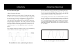
OPERATION For You Technical Types. 1. Basic Operating Principles: Whistler inverters work in two stages. During the first stage, the DC to DC converter increases the DC input voltage from the power source (e.g. a 12 volt battery) to 145 volts DC. In the second stage, the high voltage DC is converted to 110 volts (60 Hz AC) using advanced power MOSFET transistors in a full bridge configuration. The result is excellent overload capability and the capacity to operate difficult reactive loads.
OPERATING PRINCIPALS/SUMMARY In Review. • • Never attempt to operate your Whistler inverter from any power source other than a 12 volt battery or a group of batteries that total 12 volts. Always make certain that the power cable terminal connections Negative (-) to Negative (-) and Positive (+) to Positive (+). Check these connections frequently to ensure that they are secure.
TROUBLESHOOTING TROUBLESHOOTING PROBLEM: TV Interference Overload LED on Problem Solution Electrical interference from filter inverter. Add a Ferrite data line on to the TV power cord. This filter is available at electronic supply stores. PROBLEM: Low or No Output Voltage Problem Solution Using incorrect type of Use true RMS reading meter voltmeter to test output See "For You Technical voltage. Types" Section of this manual.
SPECIFICATION Pro-1200W WATT INVERTER SPECIFICATIONS Maximum Continuous Power . . . . . . . . . . . . . . . . . . . .1200 Watts Maximum Surge Capability (Peak Power) . . . . . . . . . .2400 Watts* No Load Current Draw . . . . . . . . . . . . . . . . . . . . . . . . . . . . . .< 1.0A Waveform . . . . . . . . . . . . . . . . . . . . . . . . . . . . .Modified Sine Wave Operating Input Voltage Range . . . . . . . . . . .11-15+0.5 Volts DC AC Receptacle . . . . . . . . . . . . . . .