EMPIRE Comfort Systems INSTALLATION INSTRUCTIONS AND OWNER’S MANUAL FIREPLACE INSERT Direct vent Gas Fireplace HEATER Model series DV25IN33L(N,P)-3 DV33IN33L(N,P)-3 DV35IN33L(N,P)-3 GAS-FIRED UL FILE NO. MH30033 WARNING HOT GLASS WILL CAUSE BURNS. DO NOT TOUCH GLASS UNTIL COOLED. NEVER ALLOW CHILDREN TO TOUCH GLASS. Installer: Leave this manual with the appliance. Consumer: Retain this manual for future reference.
TABLE OF CONTENTS SECTION PAGE Important Safety Information............................................................................................... 3 Safety Information for Users of LP Gas.............................................................................. 4 Introduction......................................................................................................................... 5 Specifications.....................................................................................
IMPORTANT SAFETY INFORMATION Before enclosing the vent pipe assembly, operate the appliance to ensure it is venting properly. DO NOT OPERATE THIS APPLIANCE WITHOUT GLASS FRONT PANEL INSTALLED DANGER: Indicates a hazardous situation which, if not avoided, will result in death or serious injury. • Adequate accessibility clearances for servicing and proper operation should be maintained. WARNING: Indicates a hazardous situation which, if not avoided, could result in death or serious injury.
SAFETY INFORMATION FOR USERS OF LP GAS Propane (LP-Gas) is a flammable gas which can cause fires and explosions. In its natural state, propane is odorless and colorless. You may not know all the following safety precautions which can protect both you and your family from an accident. Read them carefully now, then review them point by point with the members of your household. Someday when there may not be a minute to lose, everyone’s safety will depend on knowing exactly what to do.
INTRODUCTION Instructions to Installer 1. Installer must leave instruction manual with owner after installation. 2. Installer must have owner fill out and mail warranty card supplied with the fireplace. 3. Installer should show owner how to start and operate the fireplace. This direct vent gas fireplace heater is designed to operate with all combustion air being siphoned from the outside of the building and all exhaust gases expelled to the outside of the building.
SPECIFICATIONS DV25IN33L MODELS LP Nat Input Btu/hr Maximum 25,000 25,000 Btu/hr Minimum 17,000 17,000 FRBC Millivolt Battery Remote Thermostat Remote Control Accessories Description Millivolt Battery Remote ON/OFF KWH (Maximum) 7.30 7.30 FRBTC (Minimum) 5.00 5.00 TRW Millivolt WIRELESS Wall Thermostat #53 (0.0596) #42 (0.
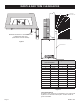
FIREPLACE INSERT DIMENSIONS • When planning a fireplace insert installation, it’s necessary to determine: • The vent system configuration to be used. • Gas supply piping. • • Whether optional accessories - devices such as a wall switch or remote control - are desired. Electrical supply requirements for blower. Proper opening size of fireplace required for installation of the fireplace insert.
MANTLE AND TRIM CLEARANCES COMBUSTIBLE MANTEL/TRIM AREA 12” A B C D E F G H I J K L M Q S V 8” U P O N R T W X Z Y MINIMUM CLEARANCE TO PERPENDICULAR COMBUSTIBLE SIDE-WALL (FROM EDGE OF DOOR FRAME) TOP OF INSERT Figure 3 SURROUND PANELS Distance from Face of Fireplace Height Above Top of Insert A 10” N 23” B 9-1/4” O 22” C 8-3/4” P 21” D 8” Q 20” E 7-1/4” R 19” F 6-1/2” S 18” G 6” T 17” H 5-1/4” U 16” I 4-1/2” V 15” J 3-3/4” W 14” K 3” X 13” L 2-1/
GAS SUPPLY The gas pipeline can be brought in through the right or left side of the appliance. The insert has a Flexline with shutoff valve located on the right side when facing the unit. See Figures 5 and 6. Consult the current National Fuel Gas Code, ANSI Z223.1 CAN/CGA-B149 (.1 or .2) installation code. Recommended Gas Pipe Diameter Pipe Length Schedule 40 Pipe Inside Diameter Tubing, Type L Outside Diameter Nat. L.P. Nat. L.P. 0-10ft 0-3m 1/2" 12.7mm 3/8" 9.5mm 1/2" 12.7mm 3/8" 9.
VENTING AND INSTALLATION 1. 2. Before beginning, remove glass door and log package from unit. Also check to make sure there is no hidden damage to the unit. Take a minute and plan out the gas, venting and electrical route. It is best to start with the gas line first, followed by the chimney liner and electrical supply requirements. Minimum fireplace opening requirements are shown in Figure 2 of this installation manual.
VENTING AND INSTALLATION Vent System Approvals Figure 8 shows the vent termination caps and systems approved for use with these models. Approved vent system terminations are labeled for identification. 3-inch diameter listed flexible aluminum or stainless steel gas vent is used for both the incoming combustion air and exhaust vent pipes. NO OTHER VENTING SYSTEMS OR COMPONENTS MAY BE USED.
VENTING AND INSTALLATION RECTANGULAR TERMINATION CAP (DVVK3FV KIT) NOTE: LONG EXTENSION TUBE FOR INLET VENT CONNECTION. ROUND TERMINATION CAP (DVKI KIT) ROUND CO-LINEAR TO CO-AXIAL ADAPTOR VENT CLAMPS RETAINER SCREWS MAY BE INSTALLED THROUGH THE VENT CLAMPS TO ENSURE POSITIVE SECUREMENT OF VENTING.
VERTICAL TERMINATION Determining Minimum Vent Height Above the Roof. WARNING Major U.S. building codes specify minimum chimney and/or vent height above the roof top. These minimum heights are necessary in the interest of safety. These specifications are summarized in Figure 9. Vertical Through the Roof Applications The Gas Fireplace Insert has been approved for: a) Vertical installations up to 35 feet in height (top of insert to cap).
ALTERNATE ON/OFF SWITCH INSTALLATION WIRING THE FIREPLACE 1. NOTICE: Electrical wiring must be installed by a licensed electrician. Find the coiled low voltage wire assembly and ON/OFF switch located in the instruction packet. 2. Attach the flag terminal ends to the “TH/TP” and “TH” terminals on the front terminal block of the gas valve. See Figure 13. CAUTION DISCONNECT REMOTE CONTROLS IF YOU ARE ABSENT FOR EXTENDED TIME PERIODS. THIS WILL PREVENT ACCIDENTAL FIREPLACE OPERATION.
SURROUND PANEL INSTALLATION INSTALLING THE TRIM SURROUNDS Combustible materials MUST NEVER overlap onto the front face. WARNING WHEN FINISHING THE FIREPLACE INSERT, NEVER OBSTRUCT OR MODIFY THE AIR INLET/OUTLET LOUVERS ON THE FIREPLACE INSERT IN ANY MANNER. NOTE: INSTALL SURROUND PANELS SO THAT THE TOP PANEL RETURN FLANGE SLIDE’S OVER THE TOP FLANGE ON THE INSERT Figure 15 ENGAGE SIDE PANEL HOOKS WITH THE NOTCHES PROVIDED ON THE SIDE FLANGES SURROUND PANEL ASSEMBLY 1” Ref.
BLOWER ACCESSORY INFORMATION The appliance, when installed must be electrically connected and grounded in accordance with local codes or, in the absence of local codes, with the current CSA C22.1 Canadian Electrical Code. U.S. Installations, follow local codes and the National Electrical Code, ANSI/NFPA No. 70. Should this blower require servicing, the power supply must be disconnected. For rewiring of any replacement components, refer to Figures 16 and 17 and the parts list on page 25.
LOG PLACEMENT Before you begin: This fireplace insert is supplied with a set of seven ceramic fiber logs. Do not handle these logs with your bare hands. Always wear gloves to prevent skin irritation from ceramic fibers. After handling logs, wash your hands gently with soap and water to remove any traces of fiber. The positioning of logs is critical to safe and clean operation of this fireplace. Sooting and other problems may result if the logs are not properly and firmly positioned in the fireplace.
OPERATING INSTRUCTIONS 750 Millivolt System The standing pilot (750 millivolt system) is a continuous burning pilot. The pilot remains ON even when the main burner is OFF. When you ignite the pilot, the thermopile produces millivolts (electrical current) which energizes the magnet in the gas valve. After 30 seconds to 1 minute time period you can release the gas control knob and the pilot will stay ON.
STANDING PILOT LIGHTING INSTRUCTIONS FOR YOUR SAFETY READ BEFORE LIGHTING Warning: If you do not follow these instructions exactly, a fire or explosion may result causing property damage, personal injury or loss of life. A. This appliance has a pilot which must be lighted by hand. When lighting the pilot, follow these instructions exactly. B. Before lighting smell all around the appliance area for gas. Be sure to smell next to the floor because some gas is heavier than air and will settle on the floor.
STANDING PILOT WIRING For Standing Pilot Ignition Wiring Optional Wall Switch Appliance Requirements Position the wall switch in the desired position on a wall. Run a maximum of 25 feet (7.8m) or less length of 18 A.W.G. minimum wire and connect it to the fireplace valve pigtails. WARNING DO NOT CONNECT 110-120 VAC TO THE GAS CONTROL VALVE OR THE APPLIANCE WILL MALFUNCTION AND THE VALVE WILL BE DESTROYED. WARNING DO NOT CONNECT THE 110-120 VAC TO THE WALL SWITCH OR THE CONTROL VALVE WILL BE DESTROYED.
STANDING PILOT TROUBLESHOOTING With proper installation and maintenance, your new Direct Vent Gas Fireplace will provide years of trouble-free service. If you do experience a problem, refer to the Trouble Shooting Guide below. This guide will assist a qualified service person in the diagnosis of problems and the corrective action to be taken. 1. Spark ignitor will not light pilot after repeated triggering of piezo ignitor button. a.
INSERT MAINTENANCE AND SERVICE Although the frequency of servicing and maintenance will depend on use and the type of installation, you should have a qualified service technician perform an appliance checkup at the beginning of each heating season. Specific guidelines regarding each appliance maintenance task are listed below. IMPORTANT: TURN OFF THE GAS BEFORE SERVICING YOUR APPLIANCE. Cleaning Burner and Controls Frequency: Once annually. By: Qualified service technician.
DECORATIVE ACCESSORIES The following accessory parts can be obtained from your Empire Comfort Systems dealer. If you need additional information beyond what your dealer can furnish, contact Empire Comfort Systems Inc., Nine Eighteen Freeburg Ave., Belleville, Illinois 62220.
INSERT PARTS VIEW 1 46 45 32 1 2 33 3 32 8 43 7 42 44 7 4 5 41 10 6 9 19 17 18 31 21 22 36 20 23 12 11 24 37 38 13 35 14 25 48 39 26 27 40 29 28 16 15 34 47 30 Page 24 30 26996-7-0411
INSERT PARTS LIST INDEX NO.
MASTER PARTS DISTRIBUTOR LIST To Order Parts Under Warranty, please contact your local Empire dealer. See the dealer locator at www.empirecomfort. com. To provide warranty service, your dealer will need your name and address, purchase date and serial number, and the nature of the problem with the unit. To Order Parts After the Warranty Period, please contact your dealer or one of the Master Parts Distributors listed below. This list changes from time to time.
APPLIANCE SERVICE HISTORY Date Dealer Name 26996-7-0411 Service Technician Name Service Performed/Notes Page 27
EMPIRE Comfort Systems Empire Comfort Systems Inc. 918 Freeburg Ave. Belleville, IL 62220 If you have a general question about our products, please e-mail us at info@empirecomfort.com. If you have a service or repair question, please contact your dealer. www.empirecomfort.