
Owner`s manual


26996-7-0411 Page 7
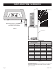
FIREPLACE INSERT DIMENSIONS
Figure 1
When planning a replace insert installation, it’s necessary to
determine:
• The vent system conguration to be used.
• Gas supply piping.
• Whether optional accessories - devices such as a wall switch
or remote control - are desired.
• Electrical supply requirements for blower.
• Proper opening size of replace required for installation of
the replace insert.
DV FIREPLACE INSERT DIMENSIONS
MODEL A B C D E F G H I J K L M N
DV25IN 19-3/4” 28 14-1/2” 11-1/8” 25-1/4” 12-3/4” 17” 18-5/16” 27” 6-3/4” 9” 20” 25-5/8” 40”
DV33IN 22-3/4” 31 16 14-1/8” 28-1/4” 14-1/4” 18-3/4” 21-5/16” 30” 8-1/4” 10-1/2” 21-1/2” 28-5/8” 43”
DV35IN 24-3/4” 34 16 16-1/8” 31-1/4” 14-1/4” 21-3/4” 23-5/16” 33” 8-1/4” 10-1/2” 23” 30-5/8” 46”
A
D
C
B
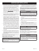
Figure 2
MINIMUM FIREPLACE OPENING DIMENSIONS
MODEL
NO.
HEIGHT
A*
FRONT
WIDTH
B
DEPTH
C
REAR
WIDTH
D
DV25IN 18-3/8” 27-1/2” 12-3/4” 17-1/4”
DV33IN 21-3/8” 30-1/2” 14-1/4” 19”
DV35IN 23-3/8” 33-1/2” 14-1/4” 22”
*NOTICE: If the replace lintel is wider than 8” (203mm), the
height of the replace opening must be increased a few inches to
allow for a gradual offset in the exhaust and/or intake vent pipes.