INSTALLATION INSTRUCTIONS AND OWNER’S MANUAL The Tahoe Direct Vent Zero Clearance Gas Fireplace Heater DIRECT VENT GAS FIREPLACE HEATER MODEL SERIES MILLIVOLT STANDING PILOT DVP36FP3(0,1,2,3)-3 NAT DVP36FP3(0,1,2,3)-3 LP INTERMITTENT PILOT DVP36FP7(0,1,2,3)-3 NAT DVP36FP7(0,1,2,3)-3 LP REMOTE RF MODELS Installer: Leave this manual with the appliance. Consumer: Retain this manual for future reference.
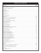
TABLE OF CONTENTS Section Page Important Safety Information .........................................................................................................................................3 Safety Information for Users of LP Gas .........................................................................................................................4 Requirements for Massachusetts.......................................................................................................................
IMPORTANT SAFETY INFORMATION Before enclosing the vent pipe assembly, operate the appliance to ensure it is venting properly. DO NOT OPERATE THIS APPLIANCE WITHOUT GLASS FRONT PANEL INSTALLED • If this appliance is installed directly on carpeting, tile or other combustible material other than wood flooring the appliance shall be installed on a metal or wood panel extending the full width and depth of the appliance. placed on or near the appliance.
SAFETY INFORMATION FOR USERS OF LP GAS by point with the members of your household. Someday when there may not be a minute to lose, everyone’s safety will depend on knowing exactly what to do. If, after reading the following information, you feel you still need more information, please contact your gas supplier. Propane (LP-Gas) is a flammable gas which can cause fires and explosions. In its natural state, propane is odorless and colorless.
REQUIREMENTS FOR MASSACHUSETTS For all side wall horizontally vented gas fueled equipment installed in every dwelling, building or structure used in whole or in part for residential purposes, including those owned or operated by the Commonwealth and where the side wall exhaust vent termination is less than seven (7) feet above finished grade in the area of the venting, including but not limited to decks and porches, the following requirements shall be satisfied: 1. INSTALLATION OF CARBON MONOXIDE DETECTORS.
INTRODUCTION Instructions to Installer 1. Installer must leave instruction manual with owner after installation. 2. Installer must have owner fill out and mail warranty card supplied with the fireplace. 3. Installer should show owner how to start and operate the fireplace. This direct vent gas fireplace heater is designed to operate with all combustion air being siphoned from the outside of the building and all exhaust gases expelled to the outside of the building.
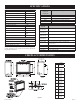
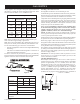
SPECIFICATIONS DVP36 Nat Models Input Btu/hr Maximum Btu/hr Minimum (millivolt only) Remote Control Options & Accessories FRBC FRBTC TMW TRW FWS-1 FREC 25,000 18,000 KWH (Maximum) 7.3 (Minimum) 5.2 Orifice #41 Air Shutter Opening 1/8" DVP36 LP Models Input Btu/hr Maximum Btu/hr Minimum (millivolt only) 27,000 Venting Options DVVK-4TSP (DVVK-4TS) DVVK-4TP (DVVK-4T) DVVK-4RP (DVVK-4R) DVVK-4VP (DVVK-4V) DVVK-4F DVVK-4RE 19,000 KWH (Maximum) 7.9 (Minimum) 5.2 Orifice 1.
CLEARANCES Mantel Chart (Figure 3) 12” (305mm) 10” (254mm) Clearance to Combustibles Back 0" (0 mm) Side 0" (0 mm) Floor 0" (0 mm) 0" (0 mm) Top Stand-off Top Framing Edge 3" (76 mm) MANTEL COMBUSTIBLE TRIM AND MANTELS ALLOWED IN SHADED AREA 8” 15” (381mm) 6” 4 ½” 3 3/4” 13 3/4” 3” 2 1/4” 11” 1 ½” 9” SEE MANTLE CHART FOR MAXIMUM MANTLE DEPTH 8” 7” 3/4” 6” 5” 2" x 4" HEADER FINISHED WALL (COMBUSTIBLE) NON-COMBUSTIBLE FIRST 3” (SEE MAGNIFFIED VIEW) 3” TOP EDGE OF FIREPLACE STAND OFF 3" (76
GAS SUPPLY The gas pipeline can be brought in through the right or left side of the appliance. Consult the current National Fuel Gas Code, ANSI Z223.1 CAN/CGA-B149 (.1 or .2) installation code. Recommended Gas Pipe Diameter Pipe Length Schedule 40 Pipe Inside Diameter Tubing, Type L Outside Diameter Nat. L.P. Nat. L.P. 0-10ft 0-3m 1/2" 12.7mm 3/8" 9.5mm 1/2" 12.7mm 3/8" 9.5mm 11-40ft 4-12m 1/2" 12.7mm 1/2" 12.7mm 5/8" 15.9mm 1/2" 12.7mm 41-100ft 13-30m 1/2" 12.7mm 1/2" 12.
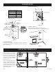
REAR VENT CONVERSION VERTICAL VENTING LP and Nat models HORIZONTAL VENTING Note: Discard insulation & retainer when venting off top of fireplace. Nat models only INLET VENT COVER PLATE Note : Discard insulation & retainer when using vertical venting off Note : It is recommended that the flue cover plate tab be pulled outward prior to removal.
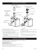
INSTALLATION Framing and Finishing 1. Choose unit location. 2. Frame in fireplace with a header across the top. It is important to allow for finished face when setting the depth of the frame. 3. Attach fireplace to frame using adjustable frame. Preset depth to suit facing material (adjustable to 1/2", 5/8" or 3/4" depths). 4. Use (8) 1/2" hex-head screws supplied in hardware package, to screw through slotted holes in drywall strip and then screw into pre-drilled holes on fireplace side.
INSTALLATION (continued) Flush Mount Mantel Installation (Figure 11) The fireplace must extend 3/4" beyond finished wall surface when using a flush mount mantel. Refer to Figure 11 to locate nailing flanges on fireplace sides. Mark and drill two (2) 1/8" holes into fireplace side to mount each nailing flange. Use eight (8) 1/2" hexhead screws supplied in hardware package to attach nailing flanges to fireplace sides. Note: For finishing to top of fireplace, refer to Figure 12.
Flush Wall Installation FINISHED WALL 3! OF NON-COMBUSTIBLE MATERIAL FRONT TRIM OR NONCOMBUSTIBLE MA TERIAL (INSTALLA TION IS OPTIONAL) JOINT BETWEEN FINISHED WALL AND UNIT SEALED WITH 300° F, 149° C SEALANT MATERIAL (Sealant is optional) Attention: Cold climate installation recommendation: When installing this unit against a non-insulated exterior wall, it is recommended that the outer walls be insulated to conform to applicable insulation codes.
INSTALLATION (continued) HORIZONTAL ONLY, STRAIGHT OUT THE BACK " A" PIPE LENGTH CORNER INSTALLATION VERTICAL, 90° ELBOW TO HORIZONTAL OUT THE WALL WALL FIRESTOP/ THIMBLE VENT CAP VENT CAP WALL FIRESTOP/ THIMBLE Nat models only "A" "B" 6" 5 1/8" to 6 1/2" 9" 8 1/8" to 9 1/2" 12" 11 1/8" to 12 1/2" LP and Nat models Dim.
VENTING FIREPLACE - TOP (LP & NAT MODELS) Venting Graph (Dimensions in Feet) To Use the Vent Graph (Figure 20) 1. Determine the height of the center of the horizontal vent pipe. Using this dimension on the Sidewall Vent Graph, locate the point it intersects with the slanted graph line. 2. From the point of this intersection, draw a vertical line to the bottom of the graph. 3. Select the indicated dimension, and position the unit in accordance with same.
VENTING FIREPLACE - TOP (continued) Below Grade Installation When it is not possible to meet the required vent terminal clearances of 12" (305mm) above grade level, a snorkel kit is recommended. It allows installation depth down to 7" (178mm) below grade level. The 7" (178mm) is measured from the center of the horizontal vent pipe as it penetrates through the wall. Ensure the sidewall venting clearances are observed.
10” (254mm) 10” (254mm) minimum LP and Nat models Figure 25 LP and Nat models Figure 24 MINIMUM HOLE LOCATION DIMENSIONS FOR THROUGH THE WALL HORIZONTAL INSTALLATIONS WITH 90 DEGREE ELBOW OFF TOP OF FIREPLACE MAXIMUM HORIZONTAL RUN WITH NO VERTICAL RISE AND 90° ELBOW FIREPLACE HARD ELBOW DIMENSIONS SERIES "A" "B" "C" DVP36FP 43-1/2" 4" 6" (1105mm) (102mm) (152mm) FIREPLACE FLEX PIPE 90 DEGREE BEND SERIES "A" "B" "C" 36FP 45" 4-1/2" 6-1/2" (165mm) (1143mm) (114mm) Positioning the Fireplace Determine t
DVVK-4FV DIRECT VENT TERMINATION KIT Installation Instructions This termination kit can only be used with Empire Comfort Systems direct vent fireplaces listed for use with DVVK-4FV Vertical Flex Vent Kit. Please review the instructions packaged with your fireplace and verify the fireplace model number. Check that this flex vent system is listed for use with your fireplace model prior to starting the installation.
PRE-INSTALLATION INFORMATION: Items Required For Installation: Tools Phillips Screwdriver Hammer Saw and/or saber saw Level Measuring Tape Electric Drill and Bits Pliers Square Tin Snips Building Supplies Framing Materials Wall Finishing Materials Caulking Material (Noncombustible) Support Strap supplies Before You Start: Plan your installation. Read these instructions and the fireplace installation manual before installing unit and vent system. Set unit in place and survey how best to vent the unit.
DVVK-4FV DIRECT VENT TERMINATION KIT (continued) Step-By-Step Installation For Flex DV Kit 1. 2. 3. 4. Unpack vent components and check all items for shipping damage. For this venting system to operate as designed it is dependent on the use of all parts and procedures detailed in these instructions. Failure to follow these instructions may potentially affect the performance of this vent system and the attached appliance.
10. With the flex vent assembly and the 48” long hard pipe components laid out on the floor, begin securing these parts together. First, apply a generous bead of silicone sealant to the inside of the 4” diameter flex flue (not the end with the pre-installaed connector), then slide the flex flue over the 4” diameter hard pipe flue. Be sure to overlap at least 1-1/4”. Secure this connection with a 4” diameter band clamp provided. Be careful not to damage or tear the flex flue when tightening clamp. 11.
DVVK-4FV DIRECT VENT TERMINATION KIT (continued) 17. To attach the vent connections at the fireplace, be sure the 7” diameter adapter collar has been installed per step 3. Apply a bead of silicone sealant to the 4” diameter flex connector, then slide the flex pipe adapter collar into the fireplace flue collar and secure by installing a minimum of two (2) screws through the flue collar and into the adapter. See Figure 31. 18.
Vertical Termination Storm Collar 4' Long Rigid Pipe Roof Flashing Adjustable Roof Jack Assembly Roof Exterior Clearance to Combustibles Required From Vent Pipe Adjustable Firestop/Thimble Assembly Ceiling Clamps At Flue & Inlet Vent Connections Storm Collar (Use TO Keep Insulation Out Of Thimble Assembly) Firestop/Thimble Venting Support Straps (As Req'd.) 35 ft. Max 4" Dia. Flue Connector Note: DVVK-4VF Kit Maximum Height (including fireplace) Is 13’.
DVVK-4FV DIRECT VENT TERMINATION KIT (continued) Vertical Flex Termination Kit Item Number 1 2 3 4 5 6 7 8 9 10 N/S N/S N/S N/S N/S Page 24 Item Description 4”/7” Vertical Termination Cap Roof Support Kit 2 Ply Alum Flex 4” Diameter by 6 ft. 2 Ply Alum Flex 7” Diameter by 6 ft.
EXAMPLES - TOP VENT RUN 24” 24” MINIMUM CLEARANCE TO COMBUSTIBLES LP and Nat models Figure 35 LP and Nat models Figure 34 LP and Nat models Figure 36 23340-4-0608 Page 25
VENTING FIREPLACE - REAR (NAT GAS MODELS ONLY) Venting Graph (Dimensions in Feet) To Use the Vent Graph (Figure 37) 1. Determine the height of the center of the horizontal vent pipe. Using this dimension on the Sidewall Vent Graph, locate the point it intersects with the slanted graph line. 2. From the point of this intersection, draw a vertical line to the bottom of the graph. 3. Select the indicated dimension, and position the unit in accordance with same.
EXAMPLES - REAR VENT RUN Model DVP36 Maximum Pipe Length H1 24" Nat models only Figure 40 Nat models only Figure 38 Model DVP36 Nat models only Figure 39 23340-4-0608 Maximum Pipe Length H1 24" Nat models only Figure 41 Page 27
TERMINATION CLEARANCES Termination clearance for buildings with combustible and noncombustible exteriors. Figure 42 Vertical Sidewall Installations Important! Minimum clearance between vent pipes and combustible materials is three (3") (76mm) on top, and (1") (25mm) on bottom and sides. Important! When vent termination exits through foundation less than 20" below siding outcrop, the vent pipe must extend outward so that the horizontal vent terminal is located flush to, or beyond the outcrop siding.
VENT CLEARANCES Figure 43 A= *Clearance above grade, veranda, porch, deck or balcony [*12 inches (30cm) minimum] B= clearance to window or door that may be opened [*12 inches (30cm) minimum for appliances < 100,000 Btuh (30kW) C= clearance to permanently closed window [minimum 12 inches (30cm) recommended to prevent condensation on window] D= vertical clearance to ventilated soffit located above the terminal within a horizontal distance of 24 inches (60 cm) from the center of the terminal [18 Inches
VENT SYSTEM IDENTIFICATION Installing Vent Components (Figure 44) Begin the vent system installation by installing the first Simpson Duravent component, 90° elbow to the starting collars or straight pipe on the top of the appliance, then the straight pipe length and then horizontal or vertical termination kit.
FRAMING AND FINISHING Installing Support Brackets (Figure 45) A horizontal pipe support MUST BE used for each 3 feet of horizontal run. The pipe supports should be placed around the pipe and nailed in place to framing members. There MUST BE a 3 inch clearance to combustibles above 6 5/8 inch diameter pipe and elbows and 1 inch clearance on both sides and bottom of 6 5/8 inch pipe to combustibles on all horizontal pipe sections and elbows.
FRAMING AND FINISHING (continued) Figure 47 Figure 49 See Horizontal Termination Page 33 and Vertical Termination Page 38-39.
HORIZONTAL TERMINATION NOTE: Termination cap should pass through the wall firestop from the exterior of the building. Adjust the termination cap to its final exterior position on the building. WARNING: Termination cap must be positioned so that arrow is pointing up. Attach the termination cap with the four wood screws provided. Before attachment of the termination, run a bead of silicone sealant rated above 250°F on its outside edge too, so as to make a seal to the exterior wall.
DVVK-4RE VENT KIT INSTALLATION INSTRUCTIONS CAUTION: Sharp edges, use protective gloves when installing. Tools Needed for Installation: Sheet metal snips 5/16” nut driver Phillips head screwdriver - #2 High temperature sealant or furnace cement rated for continuous use at 1,000oF minimum Measuring tape NOTE: SPACING FLANGE INSTALLED TO TOPSIDE 11” EXTENSION THIMBLE Parts Verification See parts list on page 36 to verify components included in this vent kit prior to installation.
DVVK-4RE VENT KIT INSTALLATION INSTRUCTIONS (continued) the opposite end. Do not crimp or enlarge tube. 8. Attach the 4” (102mm) diameter flue outlet tube onto the rigid venting system or directly to fireplace. Ensure the 4” (102mm) diameter flue outlet tube is placed as far as possible onto the rigid venting system. Mark the 4” (102mm) diameter flue outlet tube 2 1/2” (64mm) beyond the vinyl siding kit or wall. See Figure 54. Remove the 4” (102mm) diameter flue outlet tube from rigid venting system.
DVVK-4RE VENT KIT INSTALLATION INSTRUCTIONS (continued) Follow correct option according to venting method. Connecting Directly to Fireplace If the air inlet and flue outlet tubes are to be connected directly to the unit (no rigid venting system is being used), then the gasket provided must be used to seal the 4” (102mm) flue outlet tube. Peel the paper off the self-adhesive gasket and then wrap it around the end of the tube (if tube was cut, it is recommended to use cut end) as shown in Figure 56.
DVVK-4F FLEX VENT INSTRUCTIONS The DVVK-4F FLEX VENT KIT includes the following components: • (1) 7" dia. Outer Vent adapter collar • (1) Horizontal Termination Cap • (1) Wall Firestop/Thimble Assembly • (1) 4-foot section of Flex vent with spacers (4" flue/7" outer pipe) • Hardware pack that includes band clamps and screws • (1) 4" dia. Flue adapter collar Flex venting can be installed either vertically or horizontally off of the DVP36 Series fireplaces.
VERTICAL TERMINATION Locate and mark the center point of the venting pipe. Using a nail on the underside of the roof and drive this nail through this center point. Make the outline of the roof hole around this center point. When terminating the vent cap near an exterior wall or overhang, maintain minimum clearances as shown in Figure 58. NOTE: Size of the roof hole dimensions depend on the pitch of the roof. There must be a 1 inch clearance (25mm) to the vertical pipe sections.
VERTICAL TERMINATION (continued) NOTE: When installing this vent system in a chase, it is always good building practice to insulate the chase as you would the outside walls of your home. This is especially important for cold climate installations. Upon completion of building your chase framing, install the vent system by following the instructions in this manual.
LOG PLACEMENT (4 LOG SET) Before you begin: This fireplace is supplied with a set of three ceramic fiber logs. Do not handle these logs with your bare hands. Always wear gloves to prevent skin irritation from ceramic fibers. After handling logs, wash your hands gently with soap and water to remove any traces of fiber. The positioning of logs is critical to safe and clean operation of this fireplace. Sooting and other problems may result if the logs are not properly and firmly positioned in the fireplace.
OPERATING INSTRUCTIONS 750 Millivolt System The standing pilot (750 millivolt system) is a continuous burning pilot. The pilot remains ON even when the main burner is OFF. When you ignite the pilot, the thermopile produces millivolts (electrical current) which energizes the magnet in the gas valve. After 30 seconds to 1 minute time period you can release the gas control knob and the pilot will stay ON.
OPERATING INSTRUCTIONS (continued) STANDING PILOT OPERATING INSTRUCTIONS REMOTE/OFF/ON Switch The fireplace is equipped with a REMOTE/OFF/ON switch. A wire harness is attached to the REMOTE/OFF/ON switch. The red, black and green (wires) female push-ons attach to the REMOTE/OFF/ON switch. At the opposite end of the wire harness, the black and green (wires) female push-ons attach to the gas valve.
STANDING PILOT WIRING DIAGRAM (OPTIONAL) THERMOSTAT (OPTIONAL) WALL SWITCH Figure 66 23340-4-0608 Page 43
STANDING PILOT LIGHTING INSTRUCTIONS FOR YOUR SAFETY READ BEFORE LIGHTING WARNING: If you do not follow these instructions exactly, a fire or explosion may result causing property damage, personal injury or loss of life. A. This appliance has a pilot which must be lighted by hand. When lighting the pilot, follow these instructions exactly. B. Before lighting smell all around the appliance area for gas. Be sure to smell next to the floor because some gas is heavier than air and will settle on the floor.
STANDING PILOT TROUBLESHOOTING With proper installation and maintenance, your new Direct Vent Gas Fireplace will provide years of trouble-free service. If you do experience a problem, refer to the Trouble Shooting Guide below. This guide will assist a qualified service person in the diagnosis of problems and the corrective action to be taken. 1. Spark ignitor will not light pilot after repeated triggering of piezo ignitor button. a.
INTERMITTENT PILOT OPERATING INSTRUCTIONS The intermittent pilot (120/24 volt system) is ON when the main burner is ON. When the main burner is OFF the intermittent pilot is OFF. The pilot flame should envelop 3/8 to 1/2 inch (10 to 13mm) of the tip of the flame rod. To adjust: 1. Remove the pilot adjustment cover screw. 2. Turn the inner adjustment screw clockwise to decrease or counterclockwise to increase pilot flame. Pilot adjustment is shipped at full flow rate.
INTERMITTENT PILOT LIGHTING INSTRUCTIONS FOR YOUR SAFETY READ BEFORE LIGHTING WARNING: If you do not follow these instructions exactly, a fire or explosion may result causing property damage, personal injury or loss of life. A. This appliance is equipped with an ignition device which automatically lights the pilot. Do not try to light the pilot by hand. B. BEFORE LIGHTING smell all around the appliance area for gas.
INTERMITTENT PILOT TROUBLESHOOTING CALL SERVICEMAN D. Do gas leak test ahead of gas control if piping has been GENERAL: All fireplaces have been fire-tested to check for disturbed. proper operation. This includes, main burner flame, pilot flame, fan GAS LEAK TEST: Paint pipe joints with rich soap and water operation, fan control, limit control and automatic valve operation. solution. Bubbles indicate gas leak.
INTERMITTENT PILOT TROUBLESHOOTING Safety Lockout S8600H provides 100 percent shutoff, or safety lockout. A timer starts timing the moment the trial for ignition starts. Ignition spark continues only until the timed trial for ignition period ends. Then the module goes into safety lockout. Lockout de-energizes the first main valve operator and closes the first main valve in the gas control, stopping pilot gas flow.
INTERMITTENT PILOT TROUBLESHOOTING (continued) Important 1. The following service procedures are provided as a general guide. 2. Meter readings between gas control and ignition module must be taken within the trial for ignition period. Once the ignition module locks out, the system must be reset by setting the thermostat down for at least one minute before continuing. 3. If any component does not function properly, make sure it is correctly installed and wired before replacing it. 4.
INTERMITTENT PILOT TROUBLESHOOTING (continued) 23340-4-0608 Page 51
INTERMITTENT PILOT TROUBLESHOOTING (continued) Green LED Status Codes Green LED Flash Code (X + Y)a Indicates Next System Action Recommended Service Action OFF No “Call for Heat” Not applicable None Flash Fast Startup-Flame sense calibration Not applicable None Heart Beat Normal operation Not applicable None 3 Recycle - Flame failed during run Initiate new trial for ignition.
RF STANDING PILOT OPERATING INSTRUCTIONS Features • Self powered millivolt receiver/valve • Thermostat performance • Auto mode • Self powered millivolt control • Integrated Valve Electronics • Failure analysis • Pilotstat interlock • F or C temperature units Benefits • No external power or batteries required to operate valve and flame modulation • Flame cycles and modulates such that heat output equals heat loss from the room • Flame & fan are controlled automatically • No external power required to control
RF TRANSMITTER FUNCTIONS FIRST USE OF TRANSMITTER Status Action Begin communication between transmitter and receiver/valve. Move LOCAL/REMOTE Switch to LOCAL position for at least two seconds; then move switch to the REMOTE position. Transmit unique code. Press Fan or Flame key within 30 seconds. Confirm recognition between transmitter and receiver/valve. Observe LED turns on for one second. Chose Remote or Local operation. Move LOCAL/REMOTE switch to LOCAL or leave in REMOTE.
RF WIRING DIAGRAM Figure 69 23340-4-0608 Page 55
RF STANDING PILOT LIGHTING INSTRUCTIONS FOR YOUR SAFETY READ BEFORE LIGHTING WARNING: IF YOU DO NOT FOLLOW THESE INSTRUCTIONS EXACTLY, A FIRE OR EXPLOSION MAY RESULT CAUSING PROPERTY DAMAGE, PERSONAL INJURY, OR LOSS OF LIFE. A. This appliance has a pilot which must be lighted by hand. When lighting the pilot, follow these instructions exactly. B. BEFORE LIGHTING, smell around the appliance area for gas. Be sure to smell next to the floor because some gas in heavier than air and will settle on the floor.
MAINTENANCE AND SERVICE PLEASE NOTE It is normal for appliances fabricated of steel to give off some expansion and/or contraction noise during the start up or cool down cycle. Similar noises are found with your furnace heat exchanger or car engine. It is not unusual for your gas fireplace to give off some odor the first time it is burned. This is due to the curing of the paint and any undetected oil from the manufacturing process. Please ensure that your room is well ventilated - open all windows.
PARTS VIEW 1 16 2 7 19 3 4 8 5 9 11 11 6 17 12 10 12 20 18 12 21 13 14 12 15* 24 22c 27 30 31 32 33 33 32 32 34 36b 39b 40 41 MILLIVOLT BURNER ASSEMBLY 42 36c 37a 39a 37b 38 36a 34 38 35 37c 34 30 31 29 30 31 33 28 27 28 29 29 23 23 27 23 28 26 22a 26 22b 26 24 24 15 RF VALVE BURNER ASSEMBLY 50 43 47 44 45 INTERMITTENT PILOT BURNER ASSEMBLY 51 46 48 49 52 BLOWER ASSEMBLY - RF MODELS Page 58 53 LOG SET ASSEMBLY 23340-4-0608
PARTS LIST INDEX NO.
PARTS LIST (continued) INDEX NO.
FBB4 OPTIONAL VARIABLE SPEED BLOWER INSTALLATION Attention: Install blower assembly before connecting gas inlet supply line Note: Junction box on right side of fireplace must be pre-wired at time of fireplace installation for use with blower assembly. It is recommended that an ON/OFF wall switch be installed that will activate the power supply to the furnace by a qualified electrician. 1. 2. 3. 4. If installed, turn OFF gas supply to fireplace. If applicable, turn OFF electric supply to fireplace.
FBB4 OPTIONAL VARIABLE SPEED BLOWER INSTALLATION JUNCTION BOX 1 FBB4 BLOWER ASSEMBLY COMPLETE 2 R7649 FAN CONTROL 3 R4192 SPEED CONTROL KNOB 4 R4186 SPEED CONTROL 110 VOLT AC FAN BLACK FAN SWITCH WHITE SPEED CONTROL Page 62 GROUND 23340-4-0608
JUNCTION BOX WIRING INSTALLATION INSTRUCTIONS CAUTION: ALL WIRING SHOULD BE DONE BY A QUALIFIED ELECTRICIAN AND SHALL BE IN COMPLIANCE WITH ALL LOCAL, CITY AND STATE BUILDING CODES. BEFORE MAKING THE ELECTRICAL CONNECTION, MAKE SURE THAT MAIN POWER SUPPLY IS DISCONNECTED. THE APPLIANCE, WHEN INSTALLED, MUST BE ELECTRICALLY GROUNDED IN ACCORDANCE WITH LOCAL CODES OR, IN THE ABSENCE OF LOCAL CODES, WITH THE NATIONAL ELECTRICAL CODE ANSI/NFPA 70 (LATEST EDITION).
ACCESSORIES The following accessory parts can be obtained from your Empire Comfort Systems dealer. If you need additional information beyond what your dealer can furnish, contact Empire Comfort Systems Inc., Nine Eighteen Freeburg Ave., Belleville, Illinois 62220-2623. Accessory Description Model Number Variable Speed Fan Kit This fan kit was designed to provide forced air flow. (Note: For use with Millivolt and intermittent pilot models FBB4 only. "RF" Fireplace models are equipped with blower assembly.
HOW TO ORDER REPAIR PARTS Parts can be ordered only through your service person or dealer. For best results, the service person or dealer should order parts through the distributor. Parts can be shipped directly to the service person/dealer. All parts listed in the Parts List have a Part Number. When ordering parts, first obtain the Model Number from the name plate on your equipment.
SERVICE NOTES Page 66 23340-4-0608
SERVICE NOTES 23340-4-0608 Page 67
Empire Comfort Systems, Inc. 918 Freeburg Ave. Belleville, IL 62220 PH: 618-233-7420 or 800-851-3153 FAX: 618-233-7097 or 800-443-8648 info@empirecomfort.com www.empirecomfort.