
User's Manual


23340-4-0608Page 8
15”
(381mm)
TO
P EDGE OF FIREPLACE
12” (305mm)
10” (254mm)
MANTEL
COMBUSTIBLE TRIM
AND MANTELS
ALLOWED
IN SHADED AREA
4”
5”
6”
7”
8”
9”
11”
13 3/4”
3/4”
1 ½
”
2 1
/4”
3”
3 3
/4”
4 ½”
6”
8”
3”
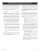
Mantel Chart (Figure 3)
Figure 3
Clearances (Figure 4)
Clearance from top of fireplace to ceiling is 36"
Clearance from side of fireplace to adjacent sidewall is 6".
Figure 4
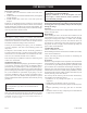
Figure 5
Note:** Island (C) and Room
Divider (D) installation is possible
as long as the horizontal portion
of the vent system (H) does not
exceed 20 feet with a minimum
vertical run of 8 feet. See details
in Venting Section.
*When you install your Direct Vent
Fireplace in (D) Room divider or
(E) Flat on wall corner positions,
a minimum of 6 inches clearance
must be maintained from the
perpendicular wall and the front
edge of the appliance.
Figure 2
Combustible Material
No greeting cards, stockings or ornamentation of any type should
be placed on or attached to the fireplace. The flow of heat can
ignite combustibles.
CABINET
INSTALLATION
FLUSH WALL
INSTALLATION
ROOM DIVIDER
INSTALLATION
CORNER
INSTALLATION
ANGLED CORNER
INSTALLATION
ISLAND
INSTALLATION
Clearance to Combustibles
Back 0" (0 mm)
Side 0" (0 mm)
Floor 0" (0 mm)
Top Stand-off
0" (0 mm)
Top Framing Edge 3" (76 mm)
SEE MANTLE CHART FOR
MAXIMUM MANTLE DEPT
H
NON-COMBUSTIBLE
FIRST 3 (SEE MAGNIFFIED
VIEW)
”
NAILIN
G
FLANGES
GLASS FRONT
TOP FRAMING
LEDGE
FINISHED WALL
(COMBUSTIBLE
)
SEE MANTLE CHART
FOR MINIMUM HEIGHT
OF MANTLE ABOVE UNI
T
2" x 4" HEADE
R
STAND
OFF
3" (76 mm) HEIGHT
ABOVE T
OP OF
FIREPLAC
E
3"
CLEARANCES
LOCATING FIREPLACE