
Owner`s manual


Page 18 12359-4-0703
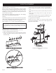
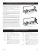
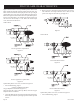
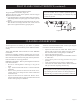
Figures 21 and 24 show a correct pilot flame pattern. The correct
flame will be blue and will extend beyond the thermocouple. The
flame will surround the thermocouple just below the tip. A slight
yellow flame may occur where the pilot flame and main burner
flame meet. Figures 22 and 25 show an incorrect pilot flame pattern.
The incorrect pilot flame is not touching the thermocouple. This
will cause the thermocouple to cool. When the thermocouple
cools, the heater will shut down.
VFSR PILOT
Correct appearance of pilot flame.
Figure 21
Incorrect appearance of pilot flame.
Figure 22
If pilot flame pattern is incorrect, as shown in Figure 22
• See Troubleshooting, page 21.
Cleaning and Maintenance/Pilot
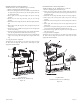
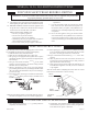
Oxygen Depletion Sensor Pilot (Figure 23 )
When the pilot has a large yellow tip flame, clean the Oxygen
Depletion Sensor as follows:
1. Clean the ODS pilot by loosening nut B from the pilot tubing.
When this procedure is required, grasp nut A with an open end
wrench.
2. Blow air pressure through the holes indicated by the arrows.
This will blow out foreign materials such as dust, lint and
spider webs. Tighten nut B also by grasping nut A.
Figure 23
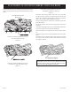
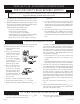
VFSV PILOT
Correct Pilot Flame Pattern
Figure 24
Incorrect Pilot Flame Pattern
Figure 25
If pilot flame pattern is incorrect, as shown in Figure 25
• See Troubleshooting, page 21.
PILOT FLAME CHARACTERISTICS