INSTALLATION INSTRUCTIONS AND OWNER’S MANUAL The Tahoe Direct Vent Zero Clearance Gas Fireplace Heater DIRECT VENT GAS FIREPLACE HEATER MODEL SERIES MILLIVOLT DVD32FP3(0,1,2,3)(N,P)-1 DVD36FP3(0,1,2,3)(N,P)-1 DVD42FP3(0,1,2,3)(N,P)-1 DVD48FP3(0,1,2,3)(N,P)-1 DIRECT IGNITION GAS-FIRED DVD32FP5(0,1,2,3)N-2 DVD36FP5(0,1,2,3)N-2 DVD42FP5(0,1,2,3)N-2 DVD48FP5(0,1,2,3)N-2 UL FILE NO. MH30033 Installer: Leave this manual with the appliance. Consumer: Retain this manual for future reference.
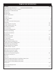
TABLE OF CONTENTS Section Page Important Safety Information ............................................................................................................................ 3 Safety Information for Users of LP Gas ............................................................................................................ 4 Requirements for Massachusetts........................................................................................................................ 5 Introduction .......
IMPORTANT SAFETY INFORMATION Before enclosing the vent pipe assembly, operate the appliance to ensure it is venting properly. DO NOT OPERATE THIS APPLIANCE WITHOUT GLASS FRONT PANEL INSTALLED • If this appliance is installed directly on carpeting, tile or other combustible material other than wood flooring the appliance shall be installed on a metal or wood panel extending the full width and depth of the appliance. The base referred to above does not mean the fireproof base as used on wood stoves.
SAFETY INFORMATION FOR USERS OF LP GAS Propane (LP-Gas) is a flammable gas which can cause fires and explosions. In its natural state, propane is odorless and colorless. You may not know all the following safety precautions which can protect both you and your family from an accident. Read them carefully now, then review them point by point with the members of your household. Someday when there may not be a minute to lose, everyone’s safety will depend on knowing exactly what to do.
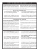
REQUIREMENTS FOR MASSACHUSETTS For all side wall horizontally vented gas fueled equipment installed in every dwelling, building or structure used in whole or in part for residential purposes, including those owned or operated by the Commonwealth and where the side wall exhaust vent termination is less than seven (7) feet above finished grade in the area of the venting, including but not limited to decks and porches, the following requirements shall be satisfied: 3. SIGNAGE.
INTRODUCTION Instructions to Installer 1. Installer must leave instruction manual with owner after installation. 2. Installer must have owner fill out and mail warranty card supplied with the fireplace. 3. Installer should show owner how to start and operate the fireplace. This direct vent gas fireplace heater is designed to operate with all combustion air being siphoned from the outside of the building and all exhaust gases expelled to the outside of the building.
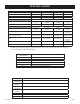
SPECIFICATIONS DVD32 18,000 14,000 5.3 4.1 DVD36 20,000 14,000 5.9 4.1 DVD42 25,000 18,000 7.3 5.3 DVD48 28,000 20,000 8.2 5.9 #46 (.081") P-254 1/16" (1.6 mm) 2.10 mm P-288 1/16" (1.6 mm) #42 (.0935") P-286 3/16"(4.8 mm) #39 (.0995") P-285 1/8" (3.2 mm) Orifice #56 (.0465") P-287 #55 (.052") P-182 1.45 mm P-208 Air Shutter Opening 1/4" (6.3 mm) 5/16" (7.
FIREPLACE DIMENSIONS RIGHT SIDE VIEW J H K Dim A B C D E F G H I J K DVD32 34" 864 mm 31" 787 mm 23 1/16" 585 mm 35 5/8" 905 mm 32 3/4" 832 mm 16 3/8" 416 mm 24 1/2" 622 mm 7 1/8" 181 mm 21 1/2" 546 mm 10 3/4" 273 mm 9 1/4" 235 mm DVD36 37" 940 mm 34" 864 mm 23 1/16" 585 mm 35 5/8" 905 mm 32 3/4" 832 mm 16 3/8" 416 mm 24 1/2" 622 mm 7 1/8" 181 mm 24 1/2" 622 mm 12 1/4" 311 mm 9 1/4" 235 mm DVD42 43" 1092 mm 40" 1016 mm 25 1/16" 636 mm 37 5/8" 956 mm 34 3/4" 883 mm 16 3/8 416 mm 26 1/2" 673 mm 7 1/8" 1
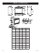
CLEARANCES Mantel Chart (Figure 3) Clearance to Combustibles Back 0" (0 mm) Side 0" (0 mm) Floor 0" (0 mm) 0" (0 mm) Top Stand-off Top Framing Edge 3" (76 mm) 12” (305mm) 10” (254mm) MANTEL SEE MANTLE CHART FOR MAXIMUM MANTLE DEPTH 15” (381mm) 2" x 4" HEADER SEE MANTLE CHART FOR MINIMUM HEIGHT OF MANTLE ABOVE UNIT COMBUSTIBLE TRIM AND MANTELS ALLOWED IN SHADED AREA 8” 6” 4 ½” STAND OFF 3" (76 mm) HEIGHT ABOVE TOP OF FIREPLACE 3 3/4” 13 3/4” 3” 2 1/4” 11” 1 ½” 9” 8” FINISHED WALL (COMBUSTIBLE
LOCATING FIREPLACE CABINET INSTALLATION CORNER INSTALLATION ISLAND INSTALLATION ANGLED CORNER INSTALLATION FLUSH WALL INSTALLATION ROOM DIVIDER INSTALLATION Note: Island (C) and Room Divider (D) installation is possible as long as the horizontal portion of the vent system (H) does not exceed 20 feet with a minimum vertical run of 8 feet. See details in Venting Section.
GAS SUPPLY The gas pipeline can be brought in through the right or left side of the appliance. Consult the current National Fuel Gas Code, ANSI Z223.1 CAN/CGA-B149 (.1 or .2) installation code. Recommended Gas Pipe Diameter Schedule 40 Pipe Tubing, Type L Inside Diameter Outside Diameter Pipe Length Nat. L.P. Nat. L.P. 0-10 feet 1/2” 3/8” 1/2” 3/8” 0-3 meters 12.7 mm 9.5 mm 12.7 mm 9.5 mm 10-40 feet 1/2” 1/2” 5/8” 1/2” 4-12 meters 12.7 mm 12.7 mm 15.9 mm 12.
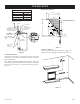
REAR VENT CONVERSION VERTICAL VENTING HORIZONTAL VENTING Note: Discard insulation & retainer when venting off top of fireplace. INLET VENT COVER PLATE Note : Discard insulation & retainer when using vertical venting off Note : It is recommended that the flue cover plate tab be pulled outward prior to removal. FLUE COVER PLATE INLET VENT COLLAR INSULATION RETAINER FLUE OUTLET COLLAR This will ensure that the plate is not accidentally dropped inside the rear air chamber.
INSTALLATION Framing and Finishing 1. Choose unit location. 2. Frame in fireplace with a header across the top. It is important to allow for finished face when setting the depth of the frame. 3. Attach fireplace to frame using adjustable frame. Preset depth to suit facing material (adjustable to 1/2", 5/8" or 3/4" depths). 4. Use (8) 1/2" hex-head screws supplied in hardware package, to screw through slotted holes in drywall strip and then screw into pre-drilled holes on fireplace side.
INSTALLATION (continued) Flush Mount Mantel Installation (Figure 11) The fireplace must extend 3/4" beyond finished wall surface when using a flush mount mantel. Refer to Figure 11 to locate nailing flanges on fireplace sides. Mark and drill two (2) 1/8" holes into fireplace side to mount each nailing flange. Use eight (8) 1/2" hex-head screws supplied in hardware package to attach nailing flanges to fireplace sides. Note: For finishing to top of fireplace, refer to Figure 13.
INSTALLATION (continued) Flush Wall Installation FINISHED WALL 3! OF NON-COMBUSTIBLE MATERIAL FRONT TRIM OR NONCOMBUSTIBLE MA TERIAL (INSTALLA TION IS OPTIONAL) JOINT BETWEEN FINISHED WALL AND UNIT SEALED WITH 300° F, 149° C SEALANT MATERIAL (SEALANT IS OPTIONAL) Attention: Cold climate installation recommendation: When installing this unit against a non-insulated exterior wall, it is recommended that the outer walls be insulated to conform to applicable insulation codes.
INSTALLATION (continued) HORIZONTAL ONLY, STRAIGHT OUT THE BACK " A" PIPE LENGTH VENT CAP WALL FIRESTOP/ THIMBLE "A" 6" 9" 12" "B" 5 1/8" to 6 1/2" (130 mm to 165 mm) 8 1/8" to 9 1/2" (206 mm to 241 mm) 11 1/8" to 12 1/2" (283 mm to 317 mm) Models DVD 32,36,42,48 DVD 32,36,42 DVD 32,36,42 Figure 16 VERTICAL, 90° ELBOW TO HORIZONTAL OUT THE WALL WALL FIRESTOP/ THIMBLE "A" 6" 9" 12" "B" 11 1/4" to 12 3/4" (286 mm to 324 mm) 14 1/4" to 15 3/4" (362 mm to 400 mm) 17 1/4" to 18 3/4" (438 mm to 476 mm)
INSTALLATION (continued) CORNER INSTALLATION VERTICAL, 90° ELBOW TO HORIZONTAL OUT THE WALL WALL FIRESTOP/ THIMBLE VENT CAP Dim.
VENTING FIREPLACE - TOP Venting Graph (Dimensions in Feet) To Use the Vent Graph (Figure 20) 1. Determine the height of the center of the horizontal vent pipe. Using this dimension on the Sidewall Vent Graph, locate the point it intersects with the slanted graph line. 2. From the point of this intersection, draw a vertical line to the bottom of the graph. 3. Select the indicated dimension, and position the unit in accordance with same. EXAMPLE B: If the vertical dimension from the floor of the unit is 6.
VENTING FIREPLACE - TOP (continued) Below Grade Installation When it is not possible to meet the required vent terminal clearances of 12" (305 mm) above grade level, a snorkel kit is recommended. It allows installation depth down to 7" (178 mm) below grade level. The 7" (178 mm) is measured from the center of the horizontal vent pipe as it penetrates through the wall. Ensure the sidewall venting clearances are observed.
VENTING FIREPLACE - TOP (continued) D C B V H C Cutting the Hole (Figures 24) After the fireplace has been positioned in its permanent location, the hole through the exterior wall of the house can be cut. This hole must be 10" (254mm) high x 10" (254mm) wide with its center line determined by the amount of vertical rise and horizontal run of the termination.
EXAMPLES - TOP VENT RUN 24” 24” MINIMUM CLEARANCE TO COMBUSTIBLES Figure 28 Figure 27 Figure 29 23552-5-0608 Page 21
VENTING FIREPLACE - REAR Venting Graph (Dimensions in Feet) To Use the Vent Graph (Figure 30) 1. Determine the height of the center of the horizontal vent pipe. Using this dimension on the Sidewall Vent Graph, locate the point it intersects with the slanted graph line. 2. From the point of this intersection, draw a vertical line to the bottom of the graph. 3. Select the indicated dimension, and position the unit in accordance with same.
EXAMPLES - REAR VENT RUN Model DVD32 DVD36 DVD42 DVD48 Maximum Pipe Length H1 24" 24" 24" 6" Figure 33 Figure 31 Model DVD32 DVD36 DVD42 DVD48 Figure 32 23552-5-0608 Maximum Pipe Length H1 24" 24" 18" N/A Figure 34 Page 23
TERMINATION CLEARANCES Termination clearance for buildings with combustible and noncombustible exteriors. Figure 35 Vertical Sidewall Installations Important! Minimum clearance between vent pipes and combustible materials is three (3") (76 mm) on top, and (1") (25 mm) on bottom and sides. Important! When vent termination exits through foundation less than 20" below siding outcrop, the vent pipe must extend outward so that the horizontal vent terminal is located flush to, or beyond the outcrop siding.
VENT CLEARANCES Figure 36 A= *Clearance above grade, veranda, porch, deck or balcony [*12 inches (305 mm) minimum] B= clearance to window or door that may be opened [*12 inches (305 mm) minimum for appliances < 100,000 BTU/Hr (30 kW) C= clearance to permanently closed window [minimum 12 inches (305 mm) recommended to prevent condensation on window] D= J = clearance to non-mechanical air supply inlet to building or the combustion air inlet to any other appliance [*12 inches (305 mm) minimum for appl
VENT SYSTEM IDENTIFICATION Installing Vent Components (Figure 37) Begin the vent system installation by installing the first Simpson Duravent component, 90° elbow to the starting collars or straight pipe on the top of the appliance, then the straight pipe length and then horizontal or vertical termination kit. NOTE: All outer connection joints must be sealed with aluminum tape, screws or silicone sealant rated above 300°F/149°C. The inner flue joints do not require any sealant.
FRAMING AND FINISHING Installing Support Brackets (Figure 38) A horizontal pipe support MUST BE used for each 3 feet of horizontal run. The pipe supports should be placed around the pipe and nailed in place to framing members. There MUST BE a 3 inch clearance to combustibles above 6 5/8 inch diameter pipe and elbows and 1 inch clearance on both sides and bottom of 6 5/8 inch pipe to combustibles on all horizontal pipe sections and elbows.
FRAMING AND FINISHING (continued) Vertical Firestops (Figures 40, 41 and 42) Vertical runs of this system which pass through ceilings require the use of ONE (1) ceiling firestop at the hole in each ceiling through which the vent passes. Position a plumb bob directly over the center of the vertical vent component and mark the ceiling to establish the center point of the vent. Drill a hole or drive a nail through this center point and check the floor above for any obstructions such as wiring or plumbing runs.
HORIZONTAL TERMINATION NOTE: Termination cap should pass through the wall firestop from the exterior of the building. Adjust the termination cap to its final exterior position on the building. WARNING: Termination cap must be positioned so that arrow is pointing up. Attach the termination cap with the four wood screws provided. Before attachment of the termination, run a bead of silicone sealant rated above 250°F on its outside edge too, so as to make a seal to the exterior wall.
DVVK-4RE VENT KIT INSTALLATION INSTRUCTIONS CAUTION: Sharp edges, use protective gloves when installing. Tools Needed for Installation: Sheet metal snips 5/16” nut driver Phillips head screwdriver - #2 High temperature sealant or furnace cement rated for continuous use at 1,000ºF minimum Measuring tape NOTE: SPACING FLANGE INSTALLED TO TOPSIDE 11” EXTENSION THIMBLE Parts Verification See parts list on page 32 to verify components included in this vent kit prior to installation.
DVVK-4RE VENT KIT INSTALLATION INSTRUCTIONS (continued) VINYL SIDING KIT DV822 OUTSIDE MOUNTING PLATE MEASURE OUTSIDE WALL 7. Remove outside mounting plate with tube attached from wall. Mark and cut the extra length of the 6 5/8” (168 mm) diameter tube from the opposite end. Do not crimp or enlarge tube. 8. Attach the 4” (102 mm) diameter flue outlet tube onto the rigid venting system or directly to fireplace.
DVVK-4RE VENT KIT INSTALLATION INSTRUCTIONS (continued) Follow correct option according to venting method. Connecting Directly to Fireplace If the air inlet and flue outlet tubes are to be connected directly to the unit (no rigid venting system is being used), then the gasket provided must be used to seal the 4” (102 mm) flue outlet tube. Peel the paper off the self-adhesive gasket and then wrap it around the end of the tube (if tube was cut, it is recommended to use cut end) as shown in Figure 50.
DVVK-4F FLEX VENT INSTRUCTIONS The DVVK-4F FLEX VENT KIT includes the following components: • • (1) Horizontal Termination Cap (1) 4-foot section of Flex vent with spacers (4" flue/7" outer pipe) • (1) 4" diameter Flue adapter collar Flex venting can be installed either vertically or horizontally off of the DVD Series fireplaces. When installing a horizontal vent run from top connections, maintain at least ½" rise for every 12" of vent run.
VERTICAL TERMINATION Locate and mark the center point of the vent pipe using a nail on the underside of the roof. Drive the nail through the center point. Mark the outline of the roof hole around this center point. NOTE: Size of the roof hole dimensions depend on the pitch of the roof. There must be a 1 inch clearance (25 mm) to the vertical pipe sections. This clearance is to all combustible material. Cover the opening of the vent pipe and cut and frame the roof hole.
VERTICAL TERMINATION (continued) Installation of Vertical Inlet Baffle The vertical inlet baffle is to be used only in a completely vertical vent installation. The vertical inlet baffle can be used when the vertical vent rise is between 10 feet and 40 feet. To maintain the yellow flame in the main burner, purchase Vertical Inlet baffle, DVF-139 from your Empire Comfort Systems, Inc. distributor or dealer for Simpson Duravent only.
LOG PLACEMENT (5 LOG SET) Before you begin: if you are installing logs into the DVD32 or DVD36 model then this fireplace is supplied with a set of five ceramic fiber logs. Do not handle these logs with your bare hands! Always wear gloves to prevent skin irritation from ceramic fibers. After handling logs, wash your hands gently with soap and water to remove any traces of fibers. The positioning of the logs is critical to the safe and clean operation of this fireplace.
LOG PLACEMENT (7 LOG SET) Before you begin: If you are installing logs into the DVD42 or DVD48 model then this fireplace is supplied with a set of seven ceramic fiber logs. Do not handle these logs with your bare hands. Always wear gloves to prevent skin irritation from ceramic fibers. After handling logs, wash your hands gently with soap and water to remove any traces of fiber. 5 6 4 The positioning of logs is critical to safe and clean operation of this fireplace.
OPERATING INSTRUCTIONS 750 Millivolt System The standing pilot (750 millivolt system) is a continuous burning pilot. The pilot remains ON even when the main burner is OFF. The OWNER should carefully read and follow these operating instructions at all times. Lower the door assembly to view the gas controls for the fireplace. When you ignite the pilot, the thermopile produces millivolts (electrical current) which energizes the magnet in the gas valve.
OPERATING INSTRUCTIONS (continued) STANDING PILOT OPERATING INSTRUCTIONS REMOTE/OFF/ON Switch The fireplace is equipped with a REMOTE/OFF/ON switch. A wire harness is attached to the REMOTE/OFF/ON switch. The red, black and green (wires) female push-ons attach to the REMOTE/ OFF/ON switch. At the opposite end of the wire harness, the black and green (wires) female push-ons attach to the gas valve.
STANDING PILOT WIRING DIAGRAM (OPTIONAL) THERMOSTAT (OPTIONAL) WALL SWITCH Figure 60 Page 40 23552-5-0608
STANDING PILOT LIGHTING INSTRUCTIONS FOR YOUR SAFETY READ BEFORE LIGHTING WARNING: If you do not follow these instructions exactly, a fire or explosion may result causing property damage, personal injury or loss of life. A. This appliance has a pilot which must be lighted by hand. When lighting the pilot, follow these instructions exactly. B. Before lighting smell all around the appliance area for gas. Be sure to smell next to the floor because some gas is heavier than air and will settle on the floor.
STANDING PILOT TROUBLESHOOTING With proper installation and maintenance, your new Direct Vent Gas Fireplace will provide years of trouble-free service. If you do experience a problem, refer to the Trouble Shooting Guide below. This guide will assist a qualified service person in the diagnosis of problems and the corrective action to be taken. 1. Spark ignitor will not light pilot after repeated triggering of piezo ignitor button. a.
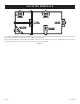
DIRECT IGNITION WIRING DIAGRAM (OPTIONAL) WALL SWITCH OR THERMOSTAT INTERRUPTEUR MURAL (FACULTATIVE) MAIN VALVE RETURN 1 GROUND 2 120V AC HOT 6 120V AC RETURN 4 13 120 VAC RTN 12 120 VAC LINE BLACK NOIR BLACK NOIR WHITE BLANC GREEN VERT JUNCTION BOX JONCTION BOÎTE Steady ON 2 Flashes 3 Flashes 4 Flashes Steady Flash GAS VALVE VALVE DE GAZ CONTROL MODULE AUTORITÉ MODULE MAIN VALVE HOT 8 (OPTIONAL) REMOTE CONTROL RECEIVER 120V (FACULATIVE) CONTROLE E DISTANCE DU RECEPTEUR SPARK IGNITOR ÉTINCE
DIRECT IGNITION LIGHTING INSTRUCTIONS FOR YOUR SAFETY READ BEFORE LIGHTING WARNING: IF YOU DO NOT FOLLOW THESE INSTRUCTIONS EXACTLY, A FIRE OR EXPLOSION MAY RESULT CAUSING PROPERTY DAMAGE, PERSONAL INJURY, OR LOSS OF LIFE. A. BEFORE LIGHTING smell all around the appliance area for gas. Be sure to smell next to the floor because some gas is heavier than air and will settle on the floor.
INITIAL START UP GAS LINE PURGE NOTE: UNIT MUST BE PROPERLY GROUNDED FOR ELECTRONIC IGNITION TO FUNCTION. On initial installation, or after extended periods where the fireplace has not been used, gas lines may require purging. The installer or qualified service person may use the following purge procedures to prevent the delays that would be caused by waiting for the lockout periods between tries for ignition. PURGE PROCEDURE 1. 2. 3. 4. Remove glass door and place away from the fireplace.
DIRECT IGNITION PROPANE/LP GAS CONVERSION The conversion shall be carried out in accordance with the requirements of the provincial authorities having jurisdiction and in accordance with the requirements of the CSA B149.2 installation code (Canada) and with the requirements of the National Fuel Gas Code Z223.1/NFPA 54 (United States).
DIRECT IGNITION PROPANE/LP GAS CONVERSION Maxitrol Valve Conversion “A” Model DVD32 DVD36 DVD42 DVD48 AIR SHUTTER SETTINGS Opening "A" 1/4" (6.4 mm) 1/4" (6.4 mm) 5/16" (7.9 mm) 5/16" (7.9 mm) BURNER ORIFICE Propane/LP Orifice #56 #55 1.
MAINTENANCE AND SERVICE PLEASE NOTE It is normal for appliances fabricated of steel to give off some expansion and/or contraction noise during the start up or cool down cycle. Similar noises are found with your furnace heat exchanger or car engine. 3. Under no circumstances should this appliance be operated without the glass front or with a broken glass front. Replacement of the glass (with gasket) as supplied by the manufacturer should be done by a qualified service person. 4.
PARTS LIST INDEX NO.
PARTS VIEW 1 2 3 4 7 8 5 11 9 10 11 12 6 16 19 13 17 13 15 13 51 14 18 13 14 15 51 28 31 32 33 28 31 32 33 40b 44 29 45 41b 39 29 40a 39 41a 34 34 37b 35 30 50 35 50 38 36 46b 48 30 37a 52 38 36 52 43 46a 47 42 MILLIVOLT BURNER ASSEMBLY 49 DIRECT IGNITION BURNER ASSEMBLY 25 20 21 26 22 24 5 PIECE ASSEMBLY 4 PIECE LOG LOG ASSEMBLY Page 50 26 20 21 27 22 24 23 PIECELOG LOGASSEMBLY ASSEMBLY 57PIECE 23552-5-0608
FBB4 OPTIONAL VARIABLE SPEED BLOWER INSTALLATION Attention: Install blower assembly before connecting gas inlet supply line Note: Junction box on right side of fireplace must be pre-wired at time of fireplace installation for use with blower assembly. It is recommended that an ON/OFF wall switch be installed that will activate the power supply to the furnace by a qualified electrician. 1. 2. 3. 4. If installed, turn OFF gas supply to fireplace. If applicable, turn OFF electric supply to fireplace.
FBB4 OPTIONAL VARIABLE SPEED BLOWER INSTALLATION 1 2 3 4 FBB4 R7649 R4192 R4186 BLOWER ASSEMBLY COMPLETE FAN CONTROL SPEED CONTROL KNOB SPEED CONTROL JUNCTION BOX 110 VOLT AC FAN BLACK FAN SWITCH WHITE SPEED CONTROL Page 52 GROUND 23552-5-0608
JUNCTION BOX WIRING INSTALLATION INSTRUCTIONS STANDARD MILLIVOLT VALVE MODELS CAUTION: ALL WIRING SHOULD BE DONE BY A QUALIFIED ELECTRICIAN AND SHALL BE IN COMPLIANCE WITH ALL LOCAL, CITY AND STATE BUILDING CODES. BEFORE MAKING THE ELECTRICAL CONNECTION, MAKE SURE THAT MAIN POWER SUPPLY IS DISCONNECTED. THE APPLIANCE, WHEN INSTALLED, MUST BE ELECTRICALLY GROUNDED IN ACCORDANCE WITH LOCAL CODES OR, IN THE ABSENCE OF LOCAL CODES, WITH THE NATIONAL ELECTRICAL CODE ANSI/NFPA 70 (LATEST EDITION).
ACCESSORIES The following accessory parts can be obtained from your Empire Comfort Systems dealer. If you need additional information beyond what your dealer can furnish, contact Empire Comfort Systems Inc., Nine Eighteen Freeburg Ave., Belleville, Illinois 62220-2623. Accessory Fan Kit Description This fan kit is designed to provide forced air flow.
DECORATIVE ACCESSORIES Decorative Louver Mission Decorative Louver Arch Decorative Louver Leaf Decorative Frame Rectangle (with hinges) Decorative Door Leaf Rectangle Decorative Door Mission Rectangle Decorative Door Plain Rectangle Decorative Frame Arch (with hinges) Decorative Door Leaf Arch Decorative Door Mission Arch Decorative Door Plain Arch Decorative Frame Arch (without hinges) (only Black) Window Trim Standard Louvers 45 Degree Outside Frame Kits 23552-5-0608 Page 55
HOW TO ORDER REPAIR PARTS Parts can be ordered only through your service person or dealer. For best results, the service person or dealer should order parts through the distributor. Parts can be shipped directly to the service person/dealer. All parts listed in the Parts List have a Part Number. When ordering parts, first obtain the Model Number from the name plate on your equipment.
SERVICE NOTES 23552-5-0608 Page 57
SERVICE NOTES Page 58 23552-5-0608
SERVICE NOTES 23552-5-0608 Page 59
EMPIRE Comfort Systems Empire Comfort Systems Inc. 918 Freeburg Ave. Belleville, IL 62220 If you have a general question about our products, please e-mail us at info@empirecomfort.com. If you have a service or repair question, please contact your dealer. www.empirecomfort.