
Operator`s manual


21
Figure 6-4
6
Maintaining
Your Lawn
Tractor
Deck Wash System™ (If equipped)
Your tractor’s deck may be equipped with a water port on
its surface as part of its deck wash system. Use the Deck
Wash System™ (sold separately) to rinse grass clippings
from the deck’s underside and prevent the buildup of cor-
rosive chemicals. Complete the following steps AFTER
EACH MOWING:
1. Drive the tractor to a level, clear spot on your lawn,
near enough to a water sillcock (spigot) for your
garden hose to reach.
IMPORTANT: Make certain the tractor’s discharge chute is
directed AWAY from your house, garage, parked cars, etc.
2. Disengage the PTO (Blade Engage), move the shift lever
into the neutral position, set the parking brake, and stop the
engine.
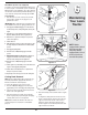
3. Thread the hose coupler (packaged with your tractor’s
Operator’s Manual) onto the end of your garden hose.
4. Attach the hose coupler to the water port on your decks
surface. See Figure 6-3.
5. Turn the water on.
6. While sitting in the operator’s position on the tractor, re-start
the engine and place the throttle lever in the FAST (rabbit)
position.
7. Disengage the parking brake.
8. Move the tractor’s PTO (Blade Engage) into the ON
position.
9. Remain in the operator’s position with the cutting deck
engaged for a minimum of two minutes, allowing the
underside of the cutting deck to thoroughly rinse.
10. Move the tractor’s PTO (Blade Engage) into the OFF
position.
11. Turn the ignition key to the STOP position to turn the tractor’s
engine off and engage the parking brake.
12. Turn the water off and detach the hose coupler from the
water port on your decks surface.
13. Repeat steps 4-11 on the opposite side of the cutting deck.
Cutting Deck Removal
NOTE: Models equipped with a 38-inch deck have one
deck idler pulley. Models equipped with a 42-inch or
46-inch deck have two deck idler pulleys.
To remove the cutting deck, proceed as follows:
1. Place the PTO (Blade Engage) lever in the disen-
gaged (OFF) position and engage the parking brake.
2. Lower the deck by moving the deck lift lever into the
bottom notch on the right fender.
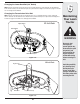
3. Remove the belt-keeper rod (B), from around the
tractor’s engine pulley, by removing the self-tapping
screw (A) that secures it. See Figure 6-4.
NOTE: Make a mental note what hole the other end
of the belt-keeper rod is inserted in for reinstallation
purposes.
Figure 6-3
A
B
C
NOTE: Models
equipped with a 38-inch
deck have one deck
idler pulley. Models
equipped with a 42-inch
or 46-inch deck have
two deck idler pulleys.
4. Remove the belt (C) from around the tractor’s engine
pulley.
5. Looking at the cutting deck from the left side of the
tractor, locate the hair pin clip that secures the deck
support rod on the rear left side of the deck. See
Figure 6-5. Remove the hair pin clip that secures
the deck support rod, and carefully remove the deck
support from the deck lift arm.
Figure 6-5